Eureka AIR delivers breakthrough ideas for toughest innovation challenges, trusted by R&D personnel around the world.

Gear mechanism for twin screw extruder

Inactive Publication Date: 2005-09-15
SIEMENS AG
View PDF4 Cites 1 Cited by
  • Summary
  • Abstract
  • Description
  • Claims
  • Application Information

AI Technical Summary

Benefits of technology

[0012] The inventive concept is characterized by a departure from the previously described known concepts having the clear spatial separation of reduction and distribution gearboxes, and is further characterized by the novel, different gear ratios between the reduction gearbox and the two output lines of the distribution gearbox.

Problems solved by technology

Particularly problematic for the operational reliability of the known gear mechanism are the two parallel herringboned gear sets in one stage.

Method used


Image

  • Gear mechanism for twin screw extruder
  • Gear mechanism for twin screw extruder
  • Gear mechanism for twin screw extruder

Examples


Embodiment Construction

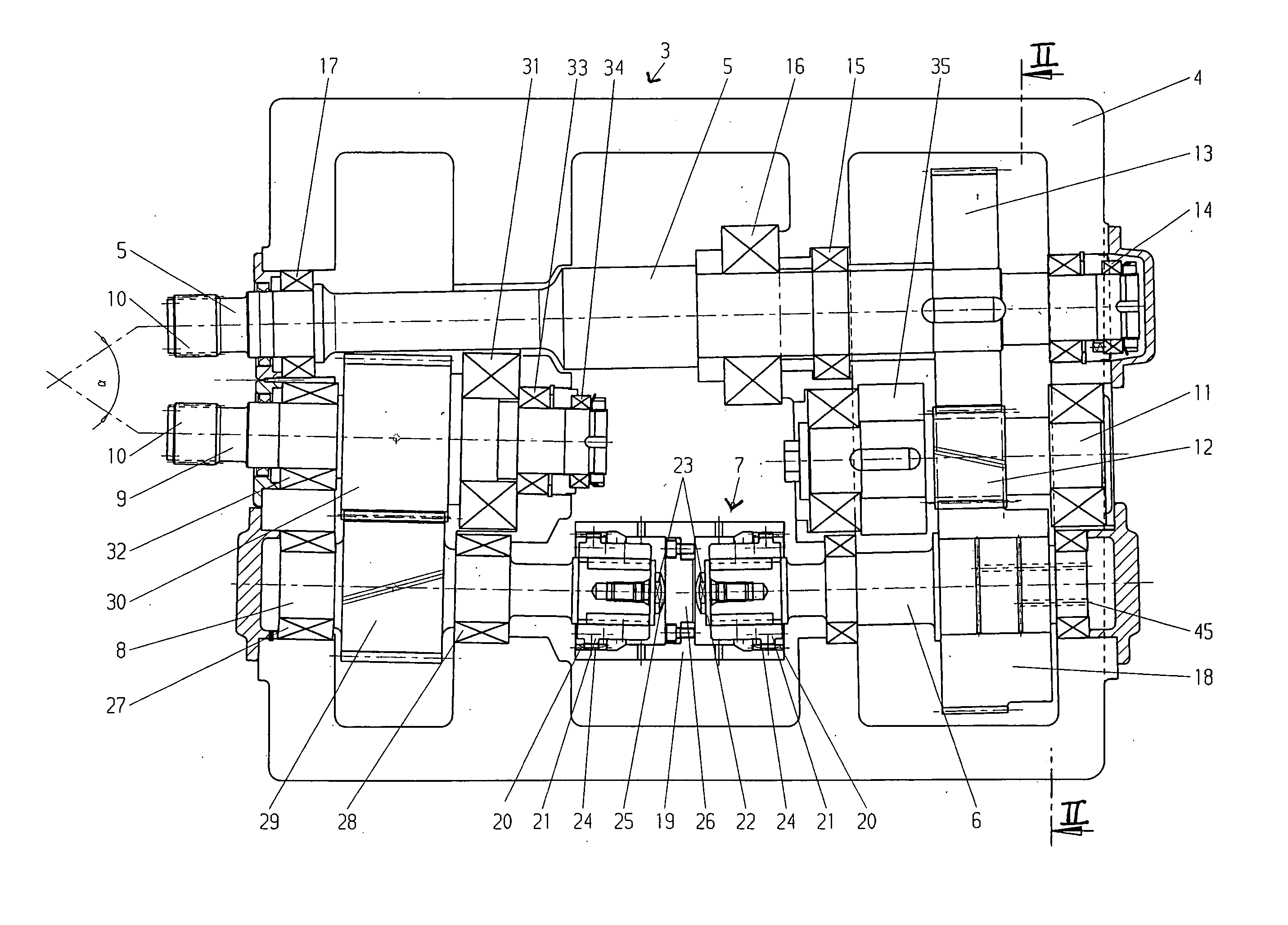
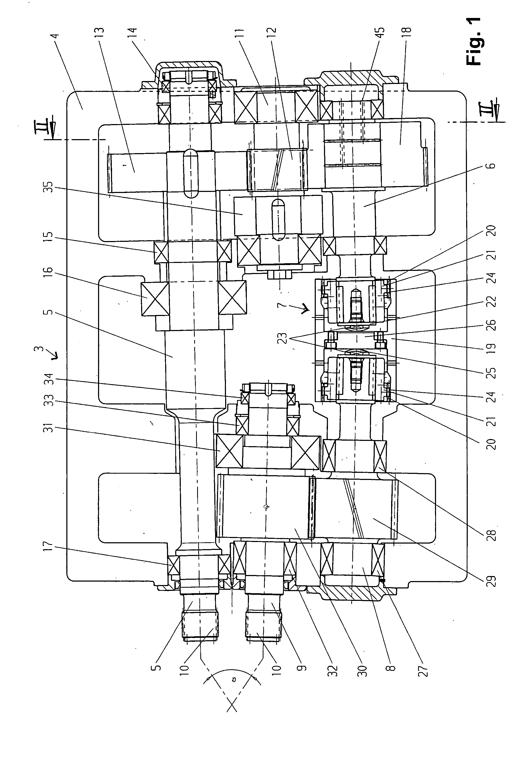
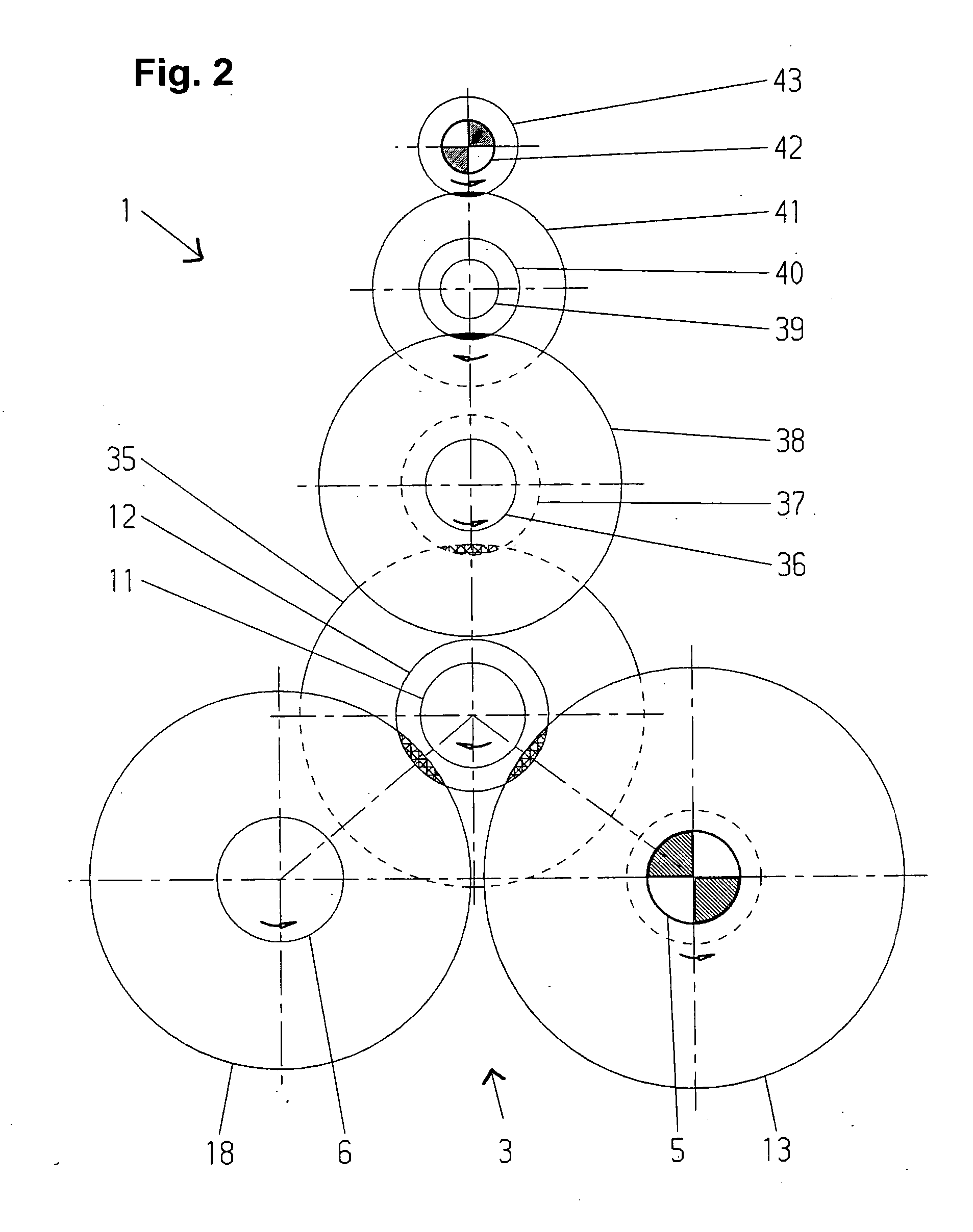
[0014] Referring now to the drawings in detail, the gear mechanism, which is to be connected to a twin worm or screw extruder, is comprised of a reduction gear mechanism or gearbox 1, which is driven by a motor 2, and a distribution gear mechanism or gearbox 3 having two output lines. The reduction gearbox 1 and the distribution gearbox 3 are accommodated in a gearbox housing 4.

[0015] The first output line is formed by a continuous or through first output shaft 5. The second output line is comprised of a first partial shaft 6, a second partial shaft 8 that is connected with the first partial shaft 6 via a coupling 7, and a second output shaft 9. The ends of the first and of the second output shafts 5, 9 are respectively provided with a coupling toothing 10 via which the ends are to be connected with the non-illustrated screw shafts of the twin screw extruder. The screw shafts are disposed at an angle α of a conicity relative to one another that is between 1° and 3°. The two output ...


PUM

PropertyMeasurementUnit
Forceaaaaaaaaaa
Angleaaaaaaaaaa
Ratioaaaaaaaaaa

Abstract

A gearbox mechanism is provided for a twin screw extruder having two screw shafts disposed at an angle to one another. The gear mechanism has a multi-stage reduction gearbox, and a distribution gearbox having two output lines connectable to the screw shafts. A first output line comprises a through output shaft. An angularly movable coupling, which is fixed against rotation, is disposed in a second output line placed at the angle of the screw shafts, relative to the first output line, via the coupling. A drive gear of the reduction gearbox is disposed between, and is in engagement with, a gear on the output shaft and a gear on a partial shaft of the second output line. A reduction gearbox and distribution gearbox are disposed, without spatial separation, in a common interior space of a multi-part gearbox housing.

Description

BACKGROUND OF THE INVENTION [0001] The present invention relates to a gear mechanism for a twin screw extruder having two screw shafts that are disposed at an angle to one another. [0002] Drive solutions for double screw extruders are characterized in the process portion, along the drive line, by the characteristic construction, beginning with a motor, a coupling, a gear drive that is to be reduced, a distribution gearbox and the extruder shafts that are coupled on. In this connection, a reduction gearbox converts not only the torque but the speed of the drive source, which is generally embodied as an electric motor. Subsequently, the distribution gearbox simultaneously distributes the drive power, up to now without further change, at a gear ratio of i=1, to both output shafts. [0003] A gear mechanism is known from DE 34 20 918 A1, where two conical, oppositely directed extruder screws are fixedly connected with the output shafts of an extruder gear mechanism. To connect the paralle...

Claims


Application Information

Patent Timeline
IPC IPC(8): B29C48/525B30B11/24F16H1/22
CPCB29C47/0009B29C47/0801B29C47/38B29C47/402Y10T74/19084B30B11/241F16H1/222Y10T74/19107B29C47/6012B29C48/03B29C48/252B29C48/395B29C48/402B29C48/525
Inventor SCHMEINK, FRANZTHEWES, HELMUT
Owner SIEMENS AG
Why Eureka
Eureka Blog
Learn More