Mobile radio terminal apparatus

a mobile radio terminal and terminal technology, applied in the direction of electrical equipment, synchronisation arrangement, connection management, etc., can solve the problems of complex hardware configuration, high power consumption of batteries, and high time consumption, and achieve the effect of saving battery power consumption and simple hardware configuration

Inactive Publication Date: 2005-09-15
KK TOSHIBA
View PDF2 Cites 18 Cited by
  • Summary
  • Abstract
  • Description
  • Claims
  • Application Information

AI Technical Summary

Benefits of technology

[0008] The present invention has been accomplished to solve the above-described problems. The object of the present invention is to provide a mobile radio terminal apparatus with a simple hardware configuration, capable and saving battery power consumption at simultaneous standby in the two radio connection schemes.
[0011] Since the constituent element to control the receive timings are integrated, the present invention can provide a mobile radio terminal apparatus with a simple hardware configuration, capable of establishing communication lines for a short time and saving battery powers consumption at simultaneous standby in the two radio connection schemes.

Problems solved by technology

In a mobile radio terminal apparatus employed in a conventional mobile radio system having two radio connection schemes, however, hardware configuration is complicated, much time is required to establish lines and much power is consumed by a battery.

Method used


Image

  • Mobile radio terminal apparatus
  • Mobile radio terminal apparatus
  • Mobile radio terminal apparatus

Examples


Embodiment Construction

[0037] An embodiment of the present invention will be explained below with reference to the accompanying drawings.

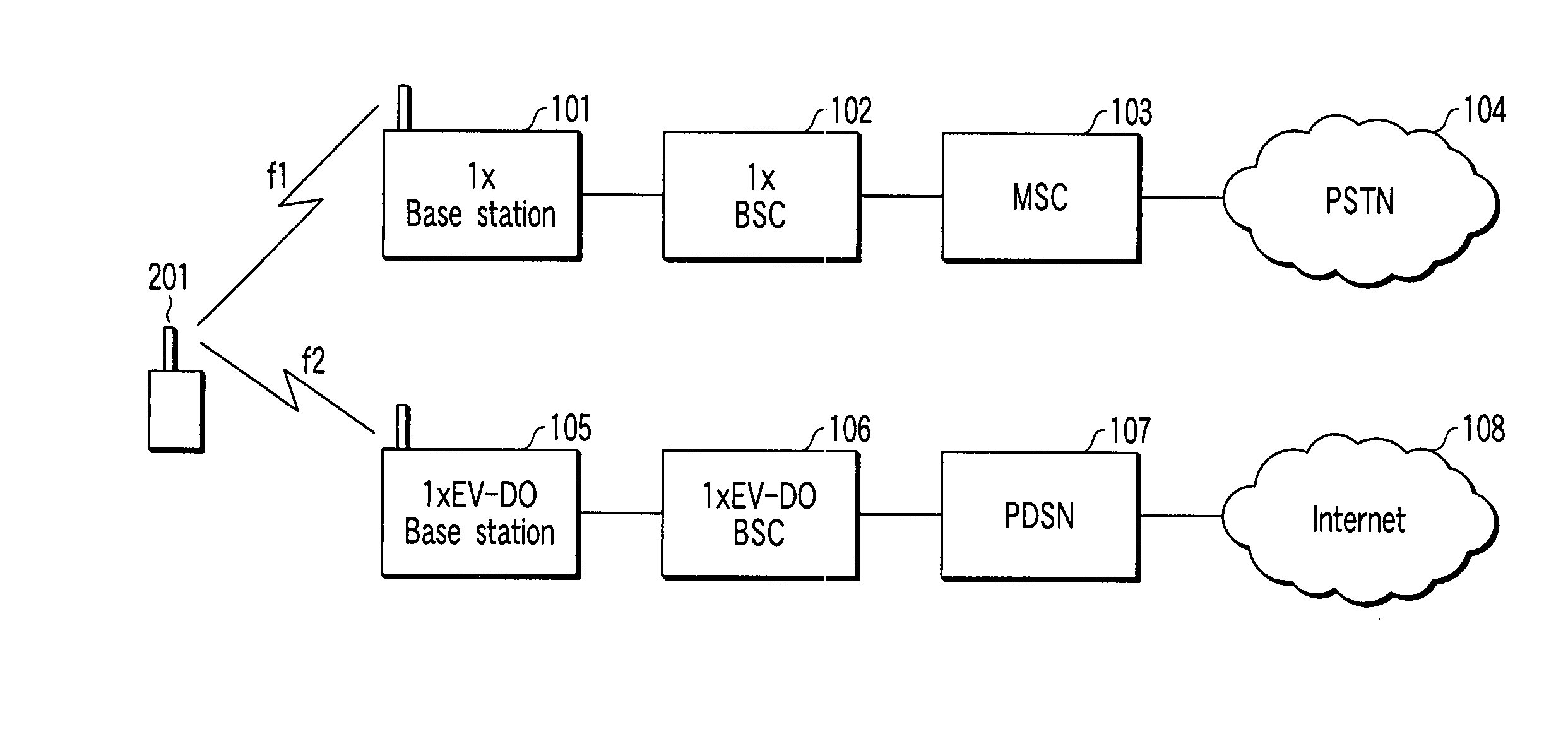
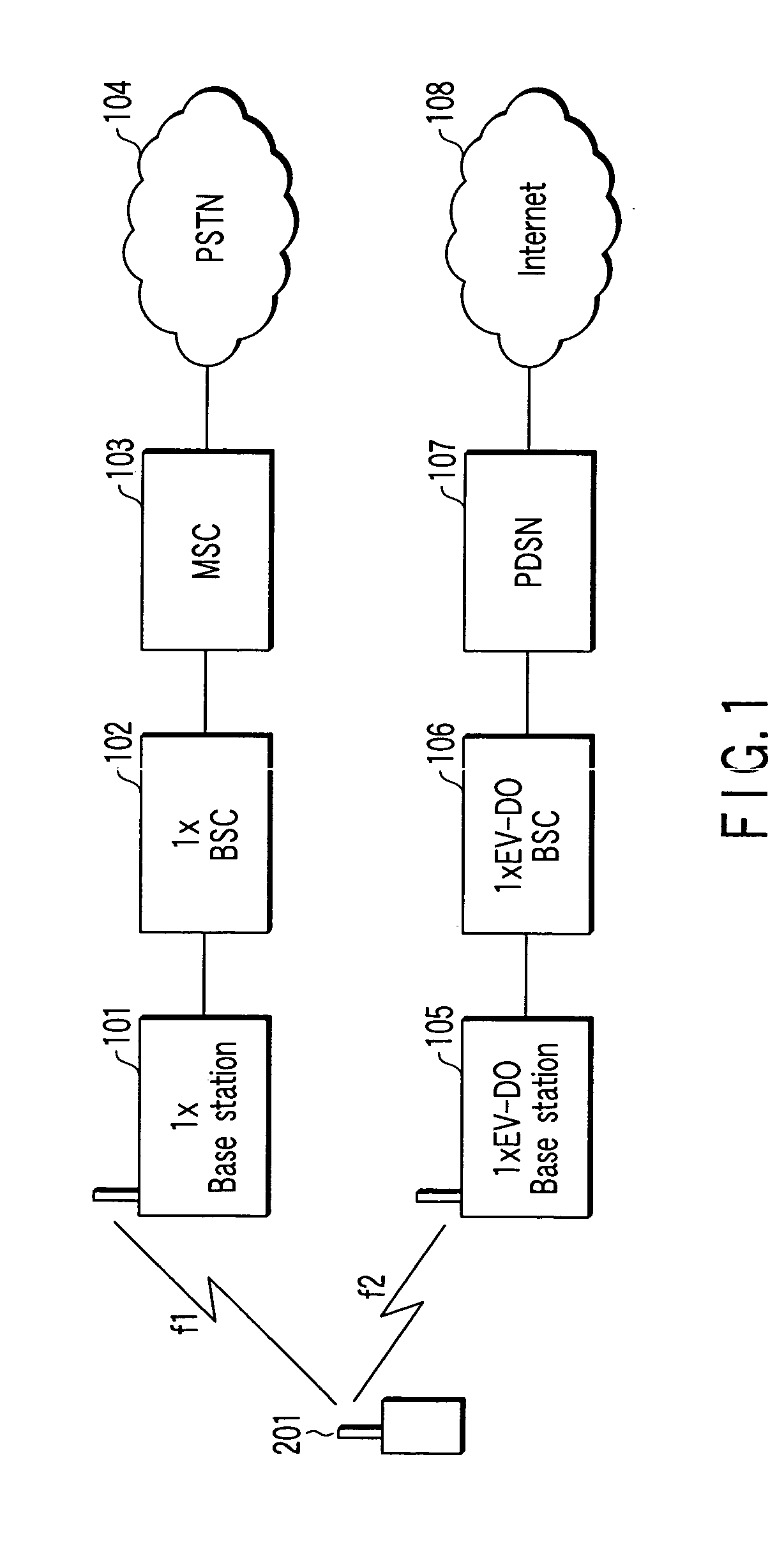
[0038]FIG. 1 shows a configuration of a mobile radio system according to the embodiment of the present invention. An example of the cdma2000 system is explained here. The present invention can be applied to not only the cdma2000 system, but also a network capable of providing a speech service as a first radio system.

[0039] The cdma2000 system is capable of making radio connection in two schemes, i.e. 1x communication scheme (hereinafter called “1x”) and 1xEV-DO communication scheme (hereinafter called “1xEV-DO”).

[0040] The 1x network includes a 1x base station 101, a 1xBSC (Base Station Controller) 102, a MSC (Mobile Switching Center) 103, a PSTN (public network) 104 and the like. The 1x service includes the speech service, SMS (Short Message Service) and the packet communication service having a download speed of about 100 kbps.

[0041] The 1xEV-DO network includes a ...


PUM


Abstract

A control unit detects a system timing from a Sync message received from a 1x base station, controls a 1x RAKE receiving unit, a 1x spreading unit, a 1xEV-DO RAKE receiving unit, and a 1xEV-DO spreading unit on the basis of detected system timing, and controls a transmit-receive timing with the 1x base station and a transmit-receive timing with the 1xEV-DO base station.

Description

CROSS-REFERENCE TO RELATED APPLICATIONS [0001] This application is based upon and claims the benefit of priority from prior Japanese Patent Application No. 2004-066987, filed Mar. 10, 2004, the entire contents of which are incorporated herein by reference.BACKGROUND OF THE INVENTION [0002] 1. Field of the Invention [0003] This invention relates to a mobile radio terminal apparatus having two radio connection schemes. [0004] 2. Description of the Related Art connection schemes, the cdma (Code Division Multiple Access) 2000 is known. [0005] The cdma2000 system is capable of making radio connection between a mobile station and a base station in two schemes, i.e. 1x communication scheme (hereinafter called “1x”) and 1xEV-DO communication scheme (hereinafter called “1xEV-DO”). [0006] In the 1x, a speech service, SMS (Short Message Service) and a packet communication service having a download speed of about 100 kbps are provided. The 1xEV-DO is employed only to provide a packet communicat...

Claims


Application Information

Patent Timeline
Patent Type & Authority Applications(United States)
IPC IPC(8): H04B1/707H04B1/7073H04B7/26H04W56/00H04W76/02H04W88/06
CPCH04W88/06H04B1/707
Inventor SAITO, NARITOSHI
Owner KK TOSHIBA
Why Eureka
Try Eureka