
Apparatus and method for digital down-conversion in a multi-mode wireless terminal

a multi-mode wireless terminal and digital down-converter technology, applied in the field of wireless networks, can solve the problems that the end-user expectations of a ubiquitous network cannot be met with mobile stations, the proliferation of wireless access standards is inconvenient and challenging for the manufacturers of wireless mobile stations (or terminals),

Inactive Publication Date: 2005-09-15
SAMSUNG ELECTRONICS CO LTD
View PDF6 Cites 19 Cited by
  • Summary
  • Abstract
  • Description
  • Claims
  • Application Information

AI Technical Summary

Benefits of technology

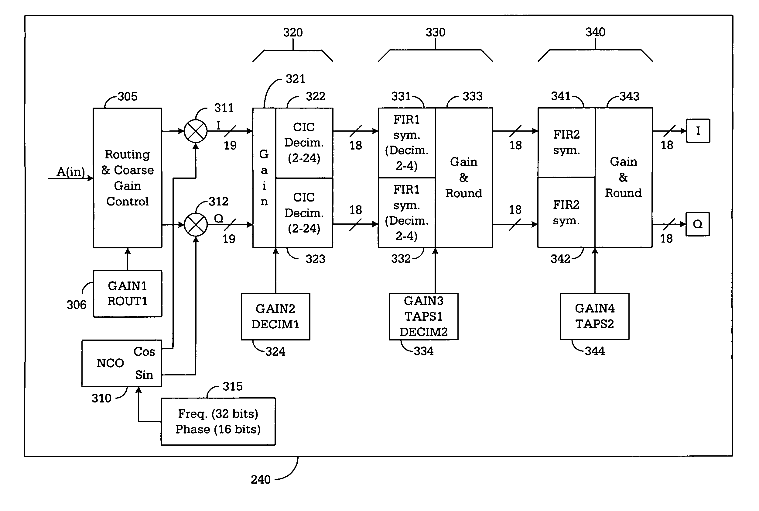
[0008] To address the above-discussed deficiencies of the prior art, it is a primary object of the present invention to provide a multi-mode digital down-converter for down-converting an incoming intermediate frequency (IF) signal to baseband level according to a selected one of a plurality of air interface standards. According to an advantageous embodiment of the present invention, the multi-mode digital down-converter comprises a re-configurable gain control block controlled by a first gain parameter capable of amplifying the incoming IF signal and a mixer stage capable of receiving and down-converting the amplified incoming IF signal to produce a first in-phase (I) baseband signal. The mixer stage receives a first reference sig...

Problems solved by technology

However, the proliferation of wireless access standards has proven to be inconvenient and challenging for the manufacturers of wireless mobile stations (or terminal), such as cell phones, PDA devices, wireless laptops, and the like.
End-user expectations of a ubiquitous network cannot be met with mobile stations that support only a subset of the possible standards.
However, such reconfigurable hardware blocks have typically been used in the modem portion of the mobile station.

Method used


Image

  • Apparatus and method for digital down-conversion in a multi-mode wireless terminal
  • Apparatus and method for digital down-conversion in a multi-mode wireless terminal
  • Apparatus and method for digital down-conversion in a multi-mode wireless terminal

Examples


Embodiment Construction

[0015]FIGS. 1 through 5, discussed below, and the various embodiments used to describe the principles of the present invention in this patent document are by way of illustration only and should not be construed in any way to limit the scope of the invention. Those skilled in the art will understand that the principles of the present invention may be implemented in any suitably arranged wireless mobile station.

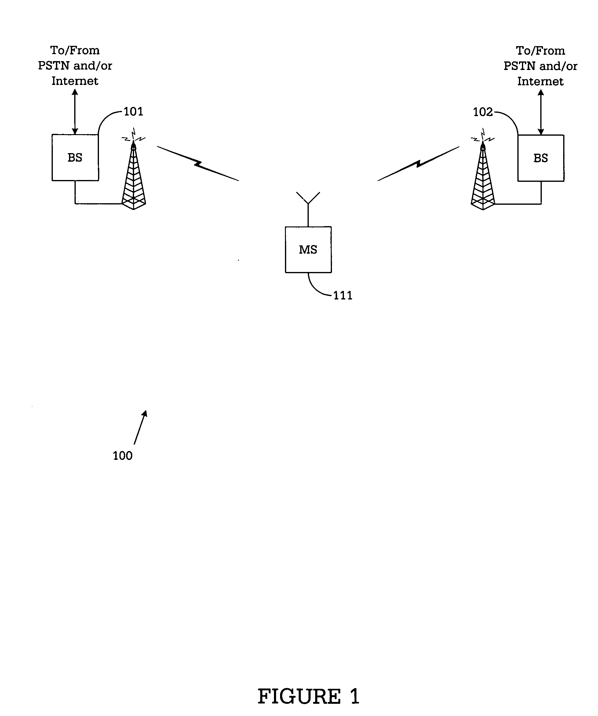
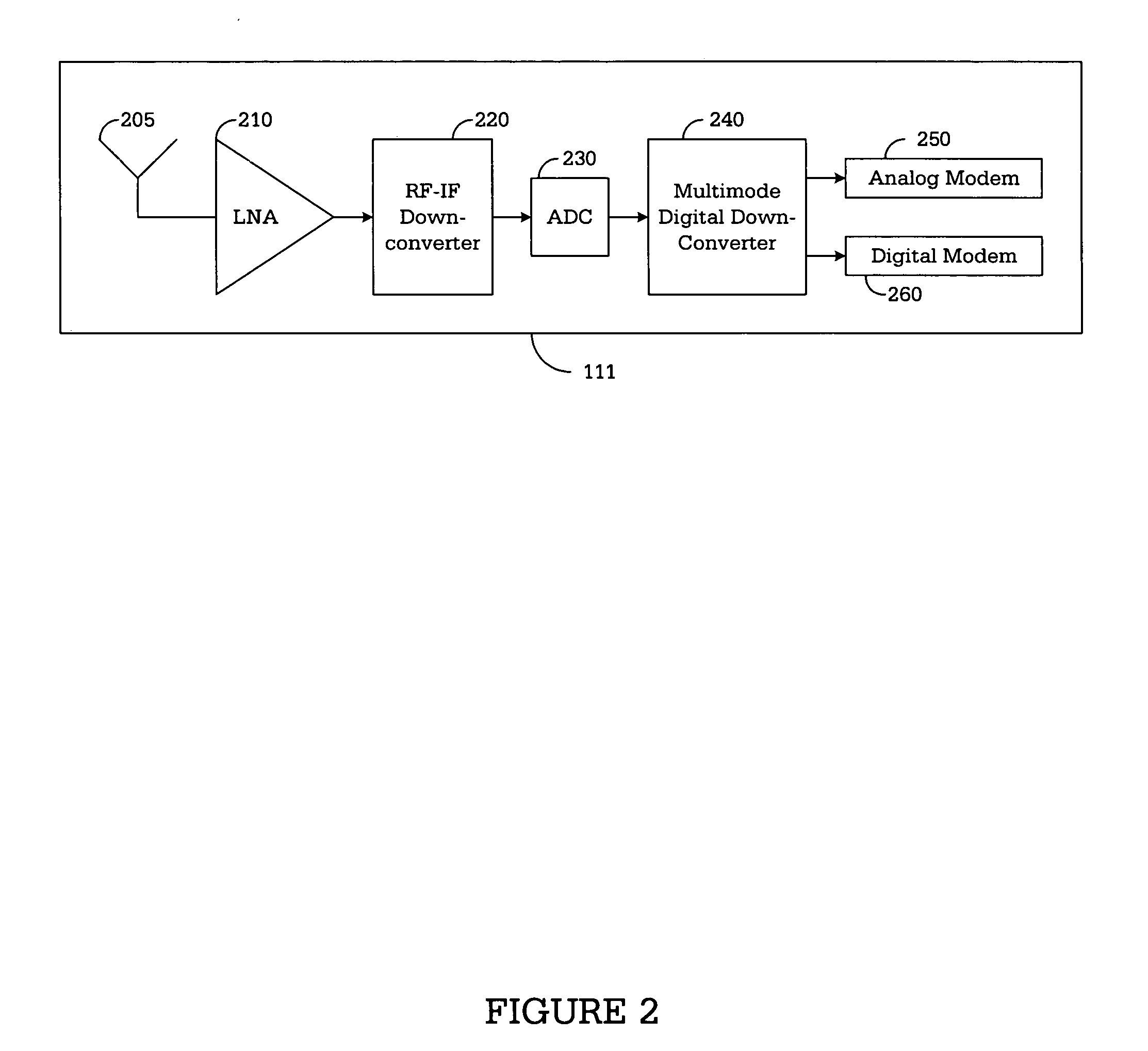
[0016]FIG. 1 illustrates wireless communication system 100, in which multi-mode mobile station (or wireless terminal) 111 may communicate with base stations operating under different air interface standards. In FIG. 1, it is assumed that base station 101 is part of a first wireless network operating according to a first air interface standard (e.g., CDMA2000 in this example). It is further assumed that base station 102 is part of a second wireless network operating according to a second air interface standard (e.g., GSM in this example). Mobile station (MS) 111 may be configur...


PUM


Abstract

A multi-mode digital down-converter for down-converting an incoming IF signal to baseband according to a selected air interface standard. The down-converter comprises a re-configurable gain control block controlled by a first gain parameter for amplifying the incoming IF signal and a mixer stage for down-converting the amplified incoming IF signal to produce a first in-phase baseband signal. The down-converter further comprises a reconfigurable CIC decimation filter block controlled by a second gain parameter and a first decimation parameter. The reconfigurable CIC decimation filter block filters the first in-phase baseband signal according to the second gain parameter and decimates the first in-phase baseband signal according to the first decimation parameter. The first and second gain parameters and the first decimation parameter are determined by the selected air interface standard.

Description

CROSS-REFERENCE TO RELATED APPLICATIONS [0001] The present invention is related to that disclosed in U.S. Provisional Patent Application Ser. No. 60 / 553,273, filed Mar. 15, 2004, entitled “Common Platform of Multi-Mode Wireless Terminal Digital Down Converter”. U.S. Provisional Patent Application Ser. No. 60 / 553,273 is assigned to the assignee of the present application. The subject matter disclosed in U.S. Provisional Patent Application Ser. No. 60 / 553,273 is hereby incorporated by reference into the present disclosure as if fully set forth herein. The present invention hereby claims priority under 35 U.S.C. §119(e) to U.S. Provisional Patent Application Ser. No. 60 / 553,273. TECHNICAL FIELD OF THE INVENTION [0002] The present invention relates generally to wireless networks and, more specifically, to multi-mode digital down-converter for use in a multi-mode mobile station that communicates with wireless networks operating under different standards. BACKGROUND OF THE INVENTION [0003...

Claims


Application Information

Patent Timeline
IPC IPC(8): H03D1/00H04L27/22
CPCH03D7/165
Inventor YOON, WEON-KI
Owner SAMSUNG ELECTRONICS CO LTD
Learn More