Image forming apparatus and control method for the image forming apparatus

a technology of image forming apparatus and control method, which is applied in the direction of electrographic process apparatus, instruments, developers, etc., can solve the problems of image failure, inability to maintain uniform charging amount, and inability to prevent image failure, so as to achieve high quality and prevent image failure

Inactive Publication Date: 2005-09-15
CANON KK
View PDF9 Cites 11 Cited by
  • Summary
  • Abstract
  • Description
  • Claims
  • Application Information

AI Technical Summary

Benefits of technology

[0029] Therefore, it is an object of the present invention to provide an image forming apparatus capable of preventing occurrence of image failure due to insufficiency in a toner charging amount and forms a high quality image, and to provide a control method for the image forming apparatus.

Problems solved by technology

However, in such an image forming apparatus using a mono-component nonmagnetic toner, deficiencies as described below may occur.
In a very early stage immediately after starting up the apparatus, in particular, in the case in which a mono-component nonmagnetic toner not using a carrier is used, image formation is started in a state in which a sufficient charge is not given to the toner and a sufficient charging amount is not obtained, or the charging amount cannot be maintained uniformly.
Thus, an image failure such as a low image density or a non-uniform image density may occur.
In addition, this phenomenon tends to occur conspicuously in a situation in which it is hard to obtain a sufficient toner charging amount, for example, in the case in which an amount of toner remaining in the developing means is large, or in a situation in which the image forming apparatus is installed in an environment of high temperature and high humidity.
Further, in such an image forming apparatus using a mono-component nonmagnetic toner, in the case in which developing means being in an unused state is used for the first time to perform image formation, deficiencies as described below may occur.
However, in an early stage of use, it is hard to coat the toner on the surface of the developing roller uniformly and, if image formation is performed in this state, image failure such as a non-uniform image density may occur.
However, in the case in which image formation is performed using developing means in an unused state., the charging amount of the toner itself in the developing means is decayed.
Thus, an image failure such as a low image density or a non-uniform image density may occur.
In particular, in a so-called contact development which is adopted in the image forming apparatus of FIG. 12, fluctuation in charging of a toner on the developing roller 111 easily becomes evident as unevenness of an image.
In addition, this phenomenon tends to occur more conspicuously in a situation in which it is hard to obtain a sufficient toner charging amount, for example, in a situation in which the image forming apparatus is installed in an environment of high temperature and high humidity.

Method used


Image

  • Image forming apparatus and control method for the image forming apparatus
  • Image forming apparatus and control method for the image forming apparatus
  • Image forming apparatus and control method for the image forming apparatus

Examples


first embodiment

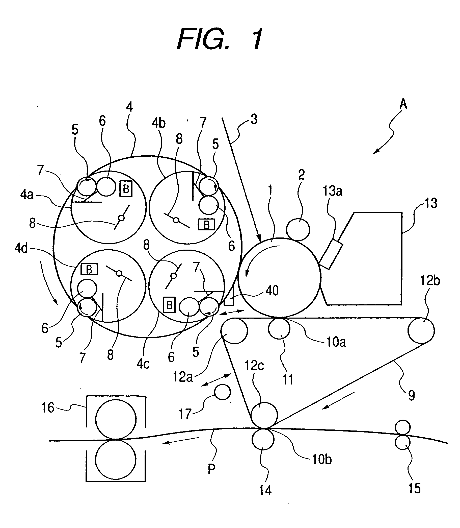
[0073] A schematic diagram of FIG. 1 shows a color image forming apparatus A which is an example of the image forming apparatus in accordance with the present invention. In FIG. 1, a photosensitive drum with a photosensitive material such as OPC (organic photoconductor) formed on an external peripheral surface of a cylinder-like base body made of aluminum is used as a photosensitive drum 1 serving as a first image bearing member. An outer diameter thereof is 50 mm. The photosensitive drum 1 is driven to rotate in a direction of arrow at a peripheral speed of 120 mm / sec.

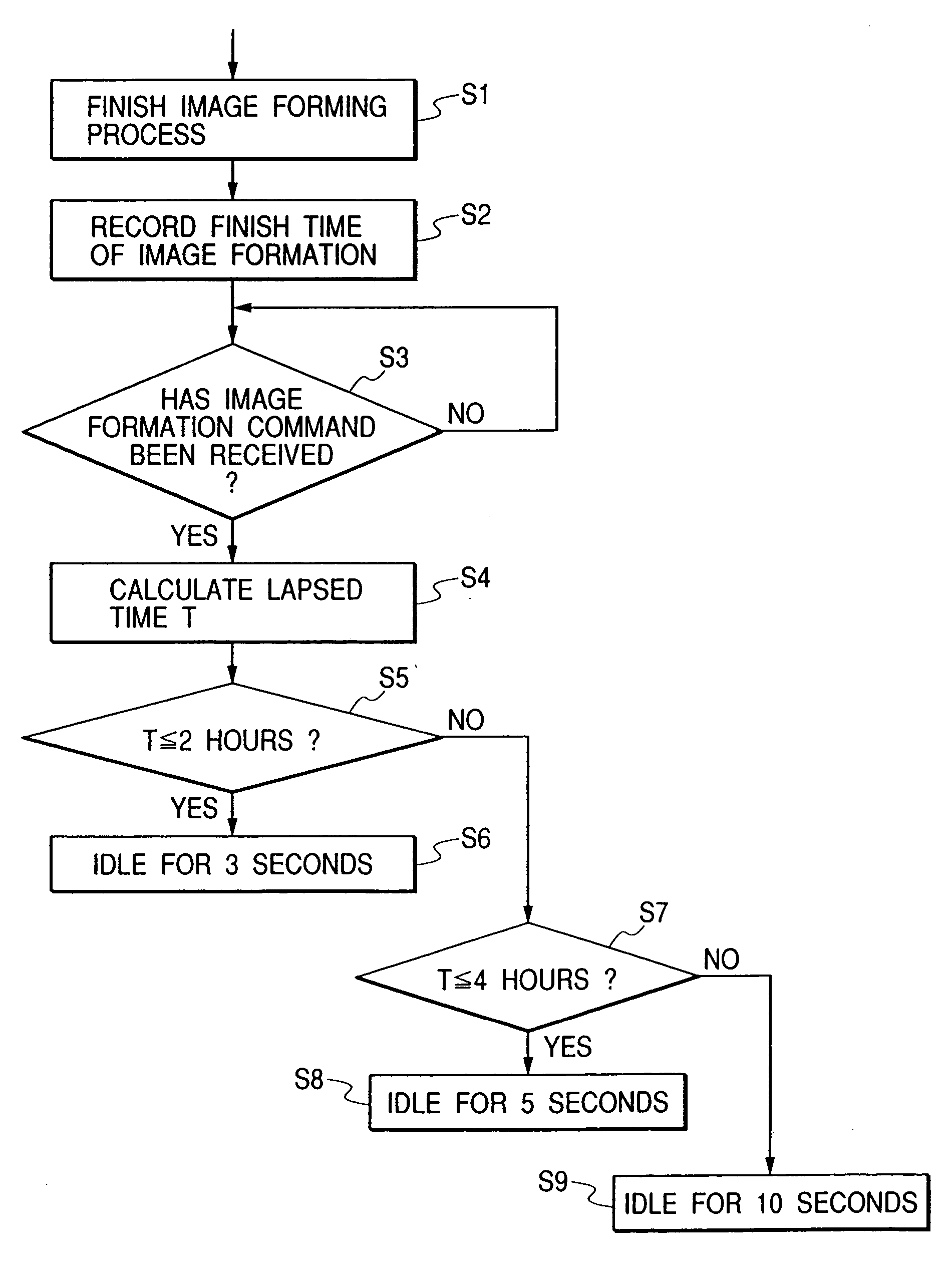
[0074] In this specification, image formation performed by the image forming apparatus is an operation for forming an electrostatic latent image on the photosensitive drum 1 based on external information, developing and visualizing the electrostatic latent image to form a developer image (toner image), and recording the developer image on a transfer material P such as paper. A process in which the image formation is ...

second embodiment

[0155] Another embodiment of the image forming apparatus and the control method therefor in accordance with the present invention will be hereinafter described. Members identical with those described in the first embodiment will be denoted by identical reference symbols, and a description thereof will be omitted.

[0156] The image forming apparatus of this embodiment is characterized in that developer remaining amount detection means (toner amount detection means) for detecting an amount of toner remaining in the respective developing devices 4a to 4d is provided, and a time for idling of the developing rollers 5 of the respective developing devices 4a to 4d, which is performed in the preparation process before image formation for one time in accordance with the control method of the image forming apparatus, is variable according to the amount of toner remaining in the respective developing devices 4a to 4d.

[0157] It is an object of this embodiment to adjust the idling time of the d...

third embodiment

[0174] Another embodiment of the image forming apparatus and the control method therefor in accordance with the present invention will be hereinafter described. Members identical with those described in the first embodiment will be denoted by identical reference symbols, and a description thereof will be omitted.

[0175] The image forming apparatus of this embodiment is characterized in that a developer remaining amount detection means, which automatically detects a temperature and humidity environmental state around a place where the image forming apparatus is installed, is provided, and a time for idling of the developing roller 5 of the respective developing devices 4a to 4d to be performed in the preparation process before image formation is variable according to environmental information detected by the developer remaining amount detection means.

[0176] It is an object of this embodiment to perform control such that excessive stress is not exerted on the toner due to an environm...


PUM


Abstract

An image forming apparatus, including: an image bearing member on a surface of which an electrostatic latent image is formed; a developing device which contains a developer and which has a rotatable developer carrying member, which abuts against the surface of the image bearing member, and a storage device storing information on image formation history, the developing device being adapted to visualize the electrostatic latent image on the surface of the image bearing member as the developer carrying member carries the developer to the electrostatic latent image; a moving mechanism which moves the developing device to one of a first position where development is performed and a second position where development is not performed; and a control device which controls, based upon the information on image formation history stored in the storage device, an operation for giving a charge to the developer according to a lapsed time from a finish time of image formation, in a state in which the developing device is moved to the second position by the moving mechanism. In the image forming apparatus, a toner is charged sufficiently in the developing device, and image failure due to insufficiency in a charging amount of toner may be prevented, thereby capable of forming a high quality image.

Description

BACKGROUND OF THE INVENTION [0001] 1. Field of the Invention [0002] The present invention relates to an image forming apparatus that uses an electrophotographic process, an electrostatic recording process, or the like and has developing means which performs a development operation with a contact development by a developer carrying member. [0003] 2. Related Background Art [0004] Conventionally, in an image forming apparatus such as a copying machine, a printer, or a facsimile apparatus provided with a function for forming an image on a recording medium, an electrostatic latent image formed on an image bearing member such as a photosensitive drum is visualized as a developer image (toner image) with developing means using a developer (toner). [0005] As such developing means, for example, a dry mono-component contact development has been proposed and put to practical use. In this system, an electrostatic latent image is often developed by bringing a rotating image bearing member (photo...

Claims


Application Information

Patent Timeline
Patent Type & Authority Applications(United States)
IPC IPC(8): G03G9/08G03G15/00G03G15/01G03G15/08G03G21/14
CPCG03G2215/0177G03G15/0863G03G15/0862G03G15/0856
Inventor TSUKIDA, SHINICHISAKAIZAWA, KATSUHIROSHIBATA, MASAHIRO
Owner CANON KK
Why Eureka
Try Eureka