Landfill structure using concept of multi-layered reactors and method for operating the same

a multi-layered reactor and landfill technology, applied in landfill technologies, construction, embankments, etc., can solve the problems of difficult to control the degradation steps of landfill b, difficult to develop the degradation of waste and the stabilization of landfill, and the reaction requisites are not provided uniformly and continuously. achieve the effect of easy control of aerobic or anaerobic degradation steps

Inactive Publication Date: 2005-09-15
ENV21
View PDF9 Cites 33 Cited by
  • Summary
  • Abstract
  • Description
  • Claims
  • Application Information

AI Technical Summary

Benefits of technology

[0021] Accordingly, the inventor of the present invention describes a brand-new landfill structure using a concept of multi-layered reactors and method for operating the same by regarding the whole landfill as a multi-layered reactors constructed as a plurality of small scale reactors are plied up. That is, according to the present invention, each of the waste layers is constructed to have a function of a single reactor and the respective reaction steps of the waste layers are processed separately, thus easily controlling aerobic or anaerobic degradation steps of the whole landfill.
[0022] Besides, the inventor of the present invention describes a brand-new landfill structure using a concept of multi-layered reactors and method for operating the same which can reduce the environmental contaminants by collecting the landfill gas generated from the landfill under declamation to make efficient use of the pas, or by oxidizing the landfill gas generated from the end covered layer by means of soil microbes.

Problems solved by technology

However, in the conventional landfill structure, the middle covered layer 30 prevents the landfill leachate and pas from moving to the respective waste layers 20 since it is made of soils or artificial materials that do not pass the landfill leachate and gas easily and hardened in a predetermined thickness when established, which makes it very difficult to develop the degradation of the waste and the stabilization of the landfill, consequently.
However, the conventional landfill 100 has several drawbacks since the landfill 100 is not treated as an assembly of the plural small scale spaces, but as a single large scale space.
However, in the conventional landfill 100 composed of the plural tight covered spaces, these reaction requisites are not provided uniformly and continuously.
In addition, when supplying the reaction regulating materials through the vertical injection wells 75 formed to penetrate into the plural waste layers 20, the reaction regulating materials are not spread in the horizontal direction uniformly since the composition of the waste is not fixed but diversified, which makes it very difficult to control the degradation steps of the landfill 100 properly.
However, according to the conventional method and structure for stabilizing the landfill 100, identical reaction requisites are provided in the whole landfill 100 since it is treated as a single tight covered space, which decreases the degradation rate of the waste and cannot even make efficient use of the landfill gas.
However, the landfill 100 applying the conventional method has a drawback that it cannot control the decomposition speed to meet the quantity required by the landfill gas recycling facilities.
Besides, the conventional method for stabilizing the landfill 100 by using aerobiosis has another drawback that the period of stabilization is lengthened according as it doesn't cope with the various reaction steps.
However, the convention landfill 100 has another drawback that it is very difficult to control the maintenance of the reaction regulating materials due to the middle covered layers 30 and the complicated composition of the waste, which takes a lot of time to stabilize the landfill 100.
That is, according to the conventional method and structure for stabilizing the landfill 100 applying a concept of “a single reactor”, it is very difficult to supply the reaction regulating materials uniformly into the whole landfill 100 due to the complicated composition of the waste and the intercepting effect of the middle covered layers 30, which delays the degradation speed of the landfill 100.
Besides, since the conventional method and structure cannot control the amount of landfill gas generated therefrom, a great deal of environmental contaminants are direct released in the air.

Method used


Image

  • Landfill structure using concept of multi-layered reactors and method for operating the same
  • Landfill structure using concept of multi-layered reactors and method for operating the same
  • Landfill structure using concept of multi-layered reactors and method for operating the same

Examples


Embodiment Construction

[0051] Reference will now be made in detail to the preferred embodiments of the present invention, examples of which are illustrated in the accompanying drawings.

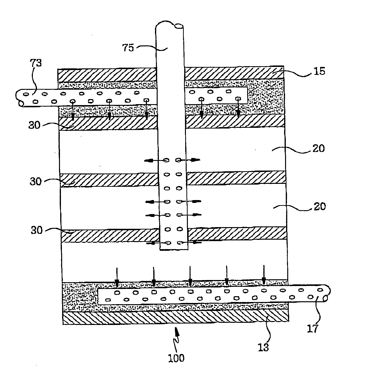
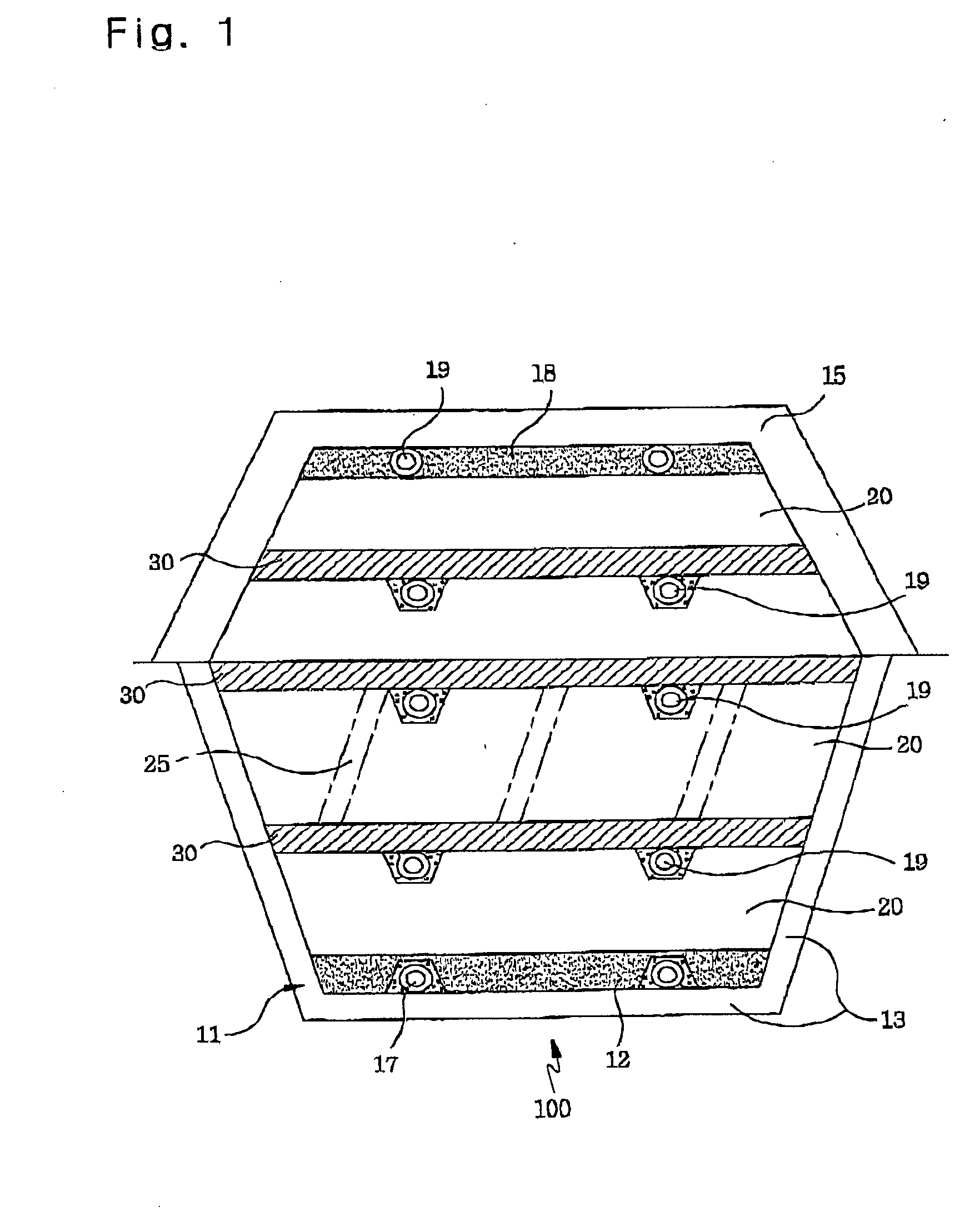
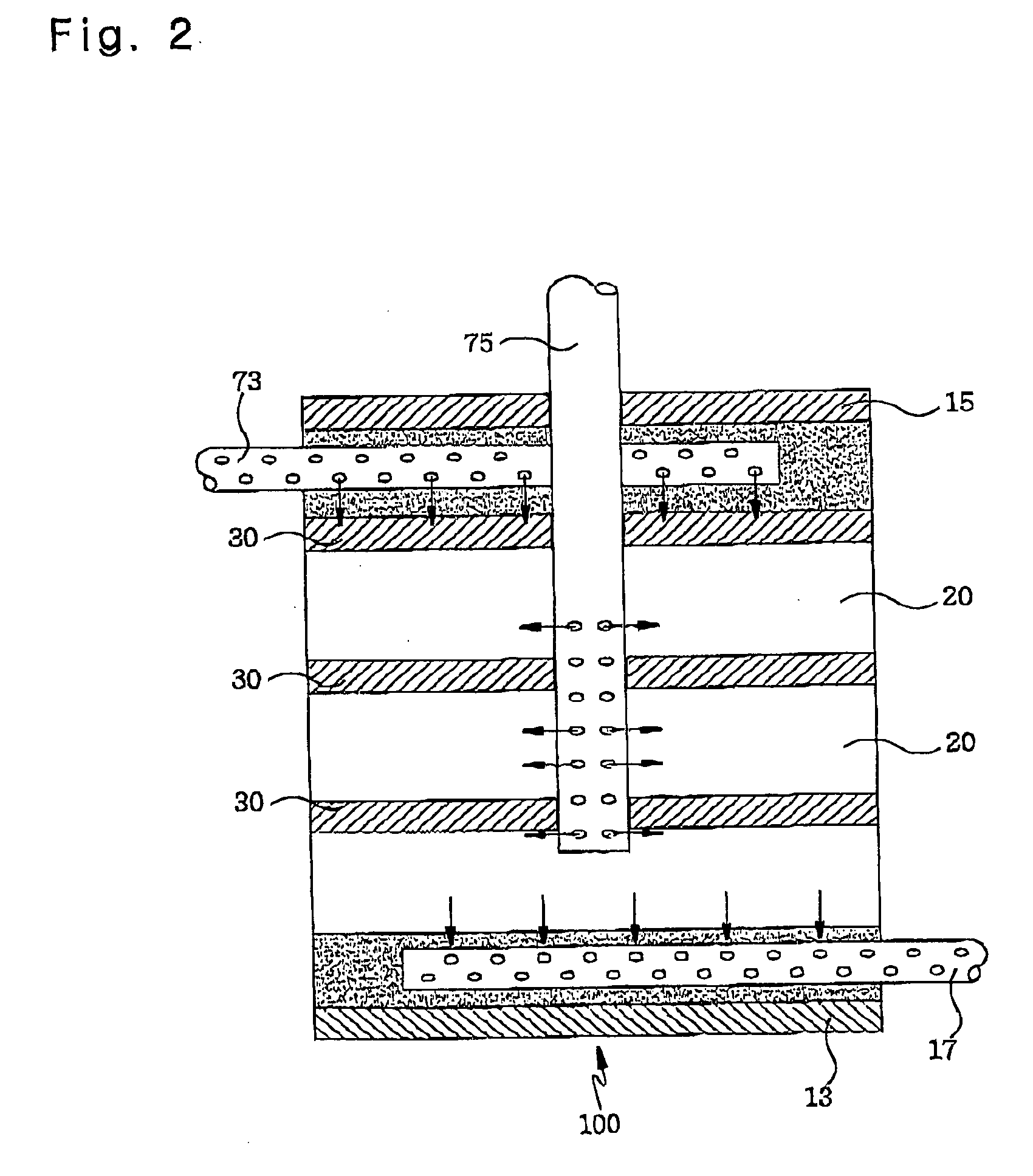
[0052] Now referring to FIG. 4a, a landfill 10 using a concept of multi-layered reactors in accordance with the present invention includes a ground waterproof layer 13, an end covered layer 15 and a plurality of waste layers 20 piled up between the two layers 13 and 15. Besides, a plurality of porous pipes 55 are established at the lower part of the respective waste layers 20 to supply reaction regulating materials, such as air, moisture, heat, nutrients, microbes, pH regulating materials, reaction inhibitors, landfill gasses, etc., or to discharge reaction products, such as leachate, landfill gas, etc., and a plurality of porous layers 45 having a predetermined thickness are provided on the porous pipes 55 to distribute the reaction regulating materials to the whole waste layers uniformly or to discharge the reaction prod...


PUM


Abstract

The invention relates to a landfill structure and a method for operating the same and, more particularly, to a landfill structure using a concept of multi-layered reactors, a method for making efficient use of landfill gas generated from the landfill, a method for early stabilizing the landfill and a method for reducing environmental contaminants generated from the landfill.

Description

TECHNICAL FIELD [0001] The present invention relates to a landfill structure and a method for operating the same and, more particularly, to a landfill structure using a concept of multi-layered reactors, a method for making efficient use of landfill gas generated from the landfill, a method for early stabilizing the landfill and a method for reducing environmental contaminants generated from the landfill. BACKGROUND ART [0002] As known well, the quantity of waste daily generated has been increased according to the industrial development, the improved standard of living, etc. There have been developed various methods for processing the waste environmentally, such as incinerating, composting and so on. However, the most waste is disposed in the landfill ultimately, which is expected that the use of the landfill will continue in the future. [0003] Referring to FIG. 1, showing an outline of an example of a conventional landfill, a base 11 is established on a lower part of a landfill 100...

Claims


Application Information

Patent Timeline
Patent Type & Authority Applications(United States)
IPC IPC(8): E02D17/18B09B1/00B09B3/00E02D31/00
CPCB09B1/00E02D31/00B09B3/00Y02W30/30E02D17/18
Inventor LEE, GEOM YONGCHO, YOUNG LAEYANG, CHANG RYUNGLEE, DONG HOONWON, YOUNG MILEE, YOUNG JOONPARK, YEON JAE
Owner ENV21
Why Eureka
Try Eureka