Gearbox mounted force generator

a force generator and gearbox technology, applied in the field of gearbox mounted force generators, can solve the problems of reducing the service life of the main gearbox, and allowing relatively large motions between the main gearbox and the airframe, so as to achieve the effect of reducing weight and small siz

Active Publication Date: 2005-09-15
SIKORSKY AIRCRAFT CORP
View PDF9 Cites 37 Cited by
  • Summary
  • Abstract
  • Description
  • Claims
  • Application Information

AI Technical Summary

Benefits of technology

[0009] Another GMFG according to the present invention replaces the differential assemblies with clutch assemblies such as magnetorheological clutches. The clutch assemblies are selectively released or engaged in response to a processor in response to changing dynamic characteristics such that vibrator

Problems solved by technology

Interrupting a load path may disadvantageously permit relatively large motions between the main gearbox and the airframe.
Interruption of the load path between the gearbox and the airframe may cause fatigue failures in high speed drive shafts that transmit shaft power from the vehicle engines to the main gearbox.
Compliant mounts may permit the gearbox to vibrate at higher levels than desirable which may then be transmitted to the driving engines reducing their service life.
Furthermore, unwanted motions may also induce unexpected control inputs by effectively defle

Method used


Image

  • Gearbox mounted force generator
  • Gearbox mounted force generator
  • Gearbox mounted force generator

Examples


Embodiment Construction

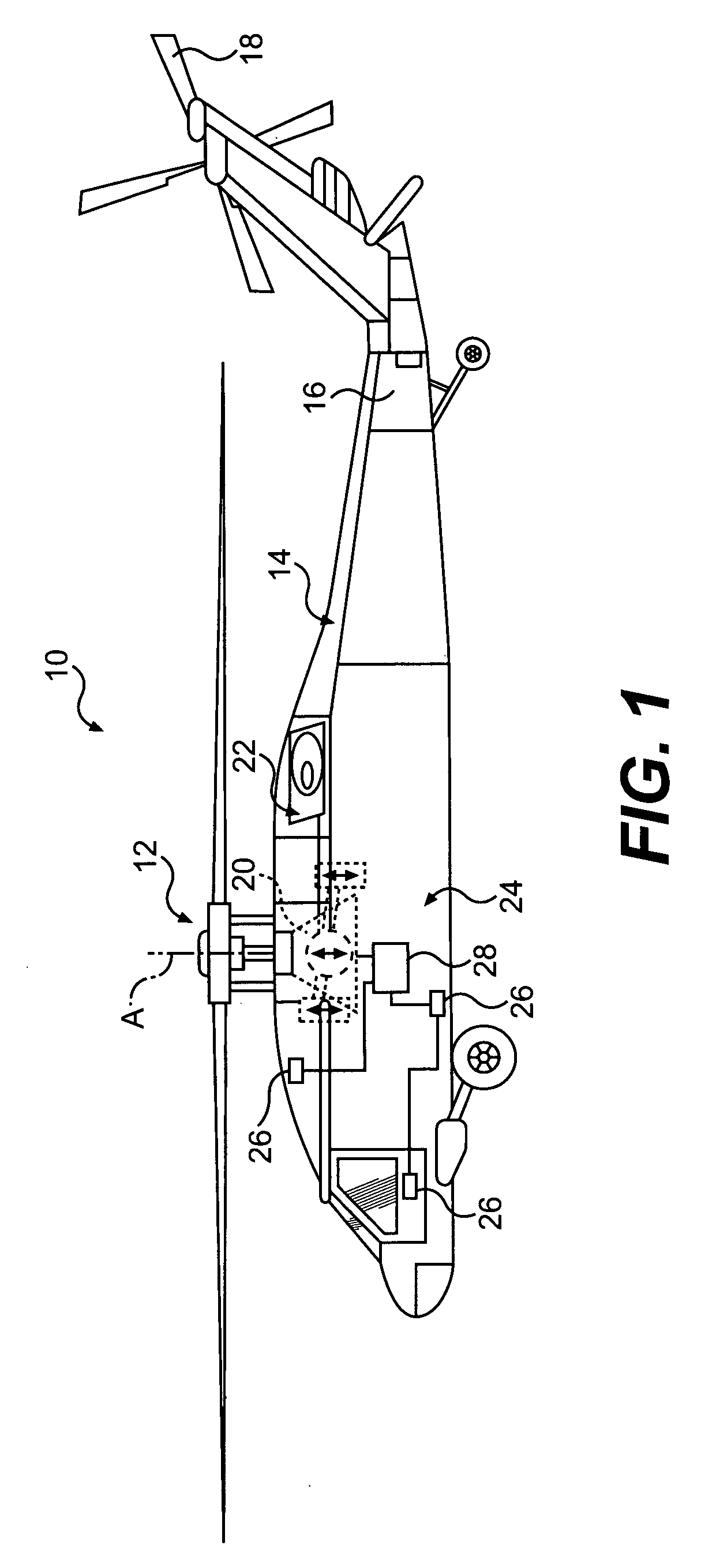
[0018]FIG. 1 schematically illustrates a rotary wing aircraft 10 having a main rotor assembly 12. The aircraft 10 includes an airframe 14 having an extending tail 16 which mounts an anti-torque rotor 18. Although a particular helicopter configuration is illustrated in the disclosed embodiment, other machines such as turbo-props and tilt-wing aircraft will also benefit from the present invention.

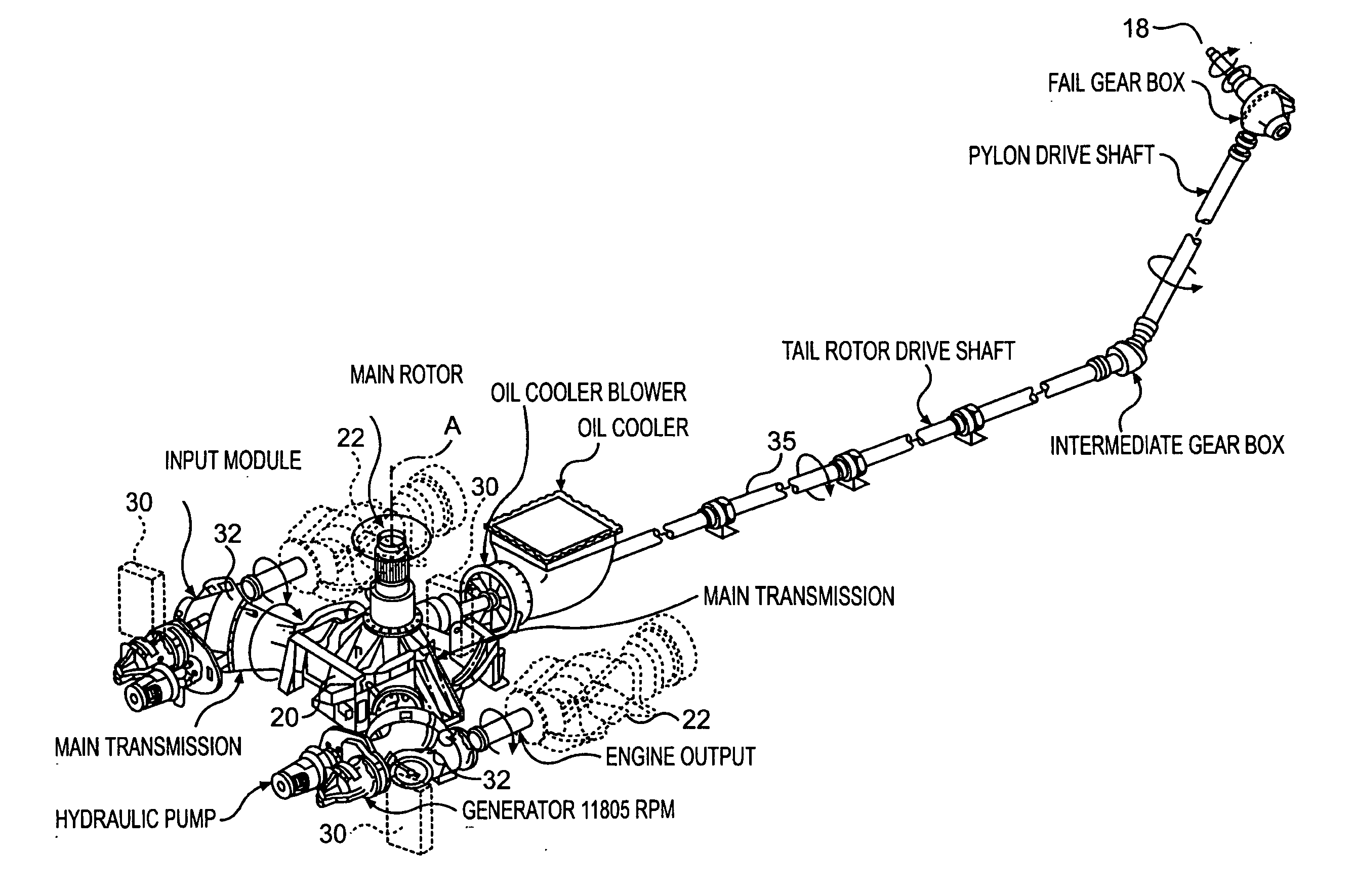
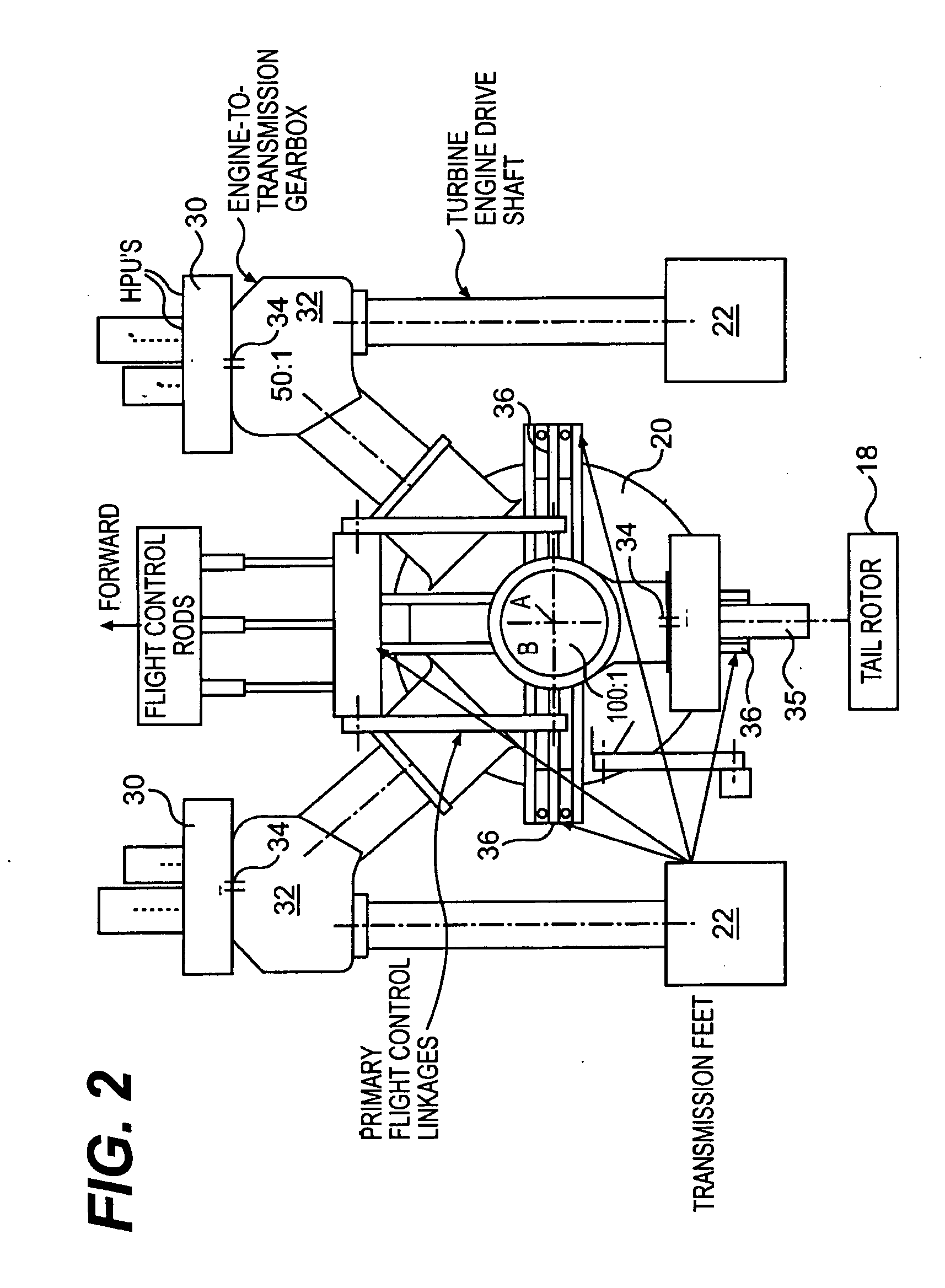
[0019] The main rotor assembly 12 is driven through a main rotor transmission (illustrated schematically at 20) by one or more engines 22. Vibrations from the rotating main rotor assembly 12, gearbox 20, and the engines 22 are thus transmitted to the helicopter airframe 14. This vibration transmission may be particularly manifested in rigid mounted gearbox systems.

[0020] An active vibration control (AVC) system 24 is mounted adjacent the gearbox 20 and is powered thereby. It should be understood that numerous locations within the aircraft 10 which also provide drive to the AVC system 24 wil...


PUM


Abstract

An active vibration control (AVC) system includes a shaft-driven gearbox mounted force generator (GMFG) mounted to a main rotor transmission. The GMFGs receive shaft power from an output shaft driven by the main rotor transmission and/or engine-to-transmission gearbox to avoid separate drive motors.

Description

BACKGROUND OF THE INVENTION [0001] The present invention relates to producing large, controllable, vibratory forces to compensate for sensed noise or vibrations, and more particularly to an active vibration control (AVC) system which is driven by an aircraft gearbox. [0002] The dominant source of vibration in a helicopter is that generated by the main rotor system rotating at the blade passing frequency. Forces and moments are transmitted usually through the transmission via airframe attachments, to produce vibration in the airframe. [0003] One conventional approach to reducing such vibration involves replacing a rigid gearbox mounting strut with a compliant strut and parallel hydraulic actuator. These actuator strut concepts “intercept” the main gearbox vibration before entry into the airframe or generate counteracting loads that partially suppress the vibration or loads. Interrupting a load path may disadvantageously permit relatively large motions between the main gearbox and the...

Claims


Application Information

Patent Timeline
IPC IPC(8): B63H1/00B64C27/00B64C27/14
CPCB64C27/001B64C27/14
Inventor WELSH, WILLIAMELLER, EREZGOODMAN, ROBERT
Owner SIKORSKY AIRCRAFT CORP
Why Eureka
Try Eureka