Battery

a battery and secondary battery technology, applied in the field of batteries, can solve the problems of difficulty in and the probability of distortion of each restriction plate, and achieve the effect of reliably suppressing a voltage drop in the secondary battery

Inactive Publication Date: 2005-09-15
NISSAN MOTOR CO LTD
View PDF10 Cites 55 Cited by
  • Summary
  • Abstract
  • Description
  • Claims
  • Application Information

AI Technical Summary

Benefits of technology

[0006] The present invention has been completed with the above studies in mind by the 10 present inventors and has an object to provide a battery that is able to achieve equalization of a surface pressure to be applied to each secondary battery for reliably suppressing a voltage drop in the secondary battery.

Problems solved by technology

Also, each restriction plate has much probability of suffering distortion due to a pressing force applied through each restriction plate when the plural secondary batteries are applied with surface pressures by the pair of restriction plates pressed by the connecting rods.
The occurrence of distortion is accompanied by a surface pressure distribution pattern in which a surface pressure decreases from an outer periphery of the secondary battery to a central area thereof with the resultant difficulty in applying a uniform surface pressure to each secondary battery, causing a difficulty in reliably suppressing a voltage drop in the secondary battery.

Method used


Image

  • Battery
  • Battery
  • Battery

Examples


first embodiment

[0038] First, a battery of a first embodiment according to the present invention is described below in detail with reference to FIGS. 1 to 8.

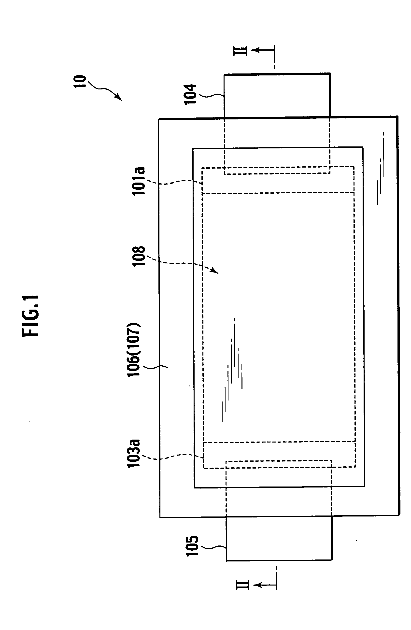
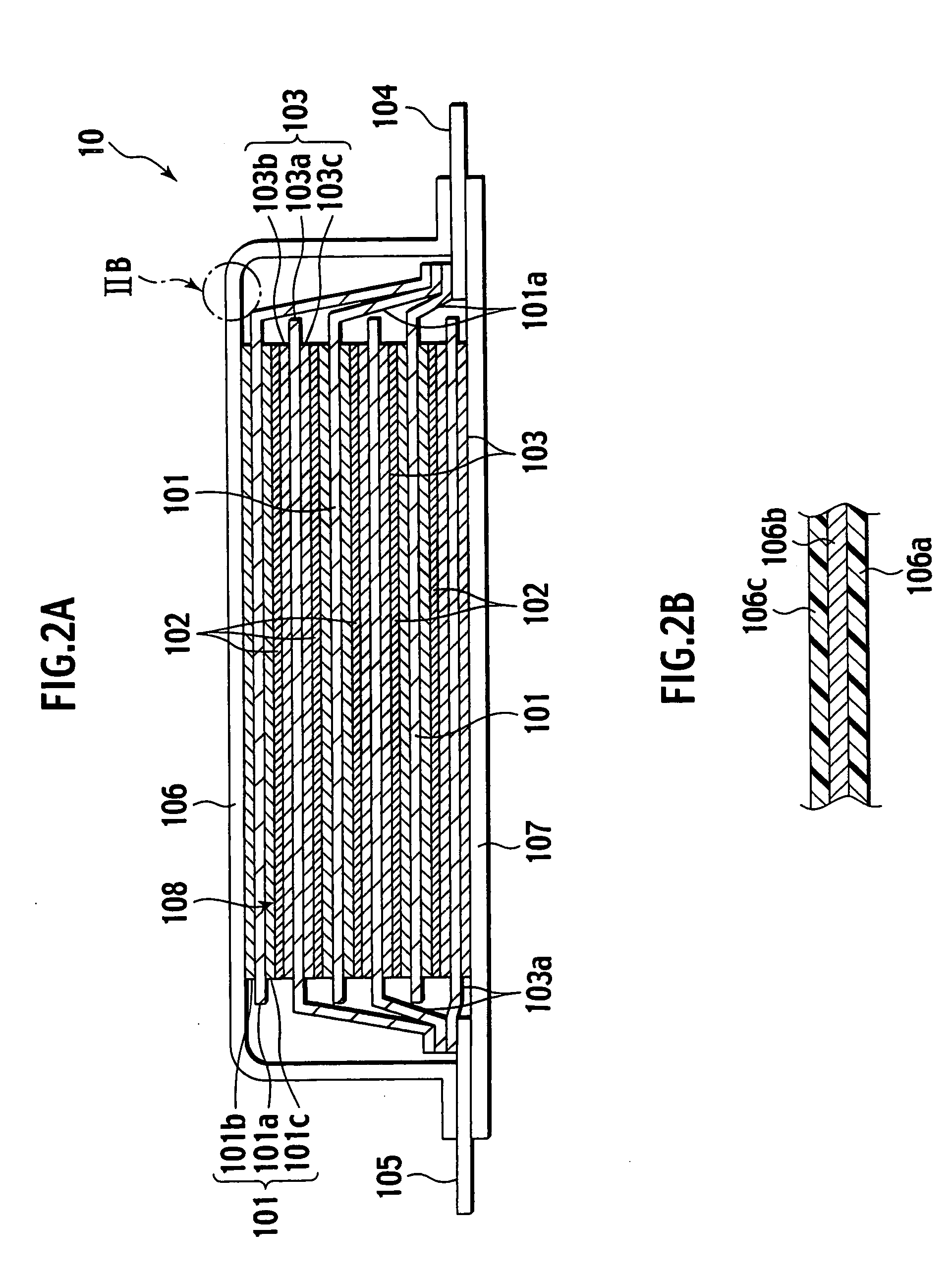
[0039]FIG. 1 is a plan view of a whole of a secondary battery of the presently filed embodiment; FIG. 2A is a cross-sectional view taken on line II-II of FIG. 1; and FIG. 2B is an enlarged cross-sectional view of a section IIB in FIG. 2A.

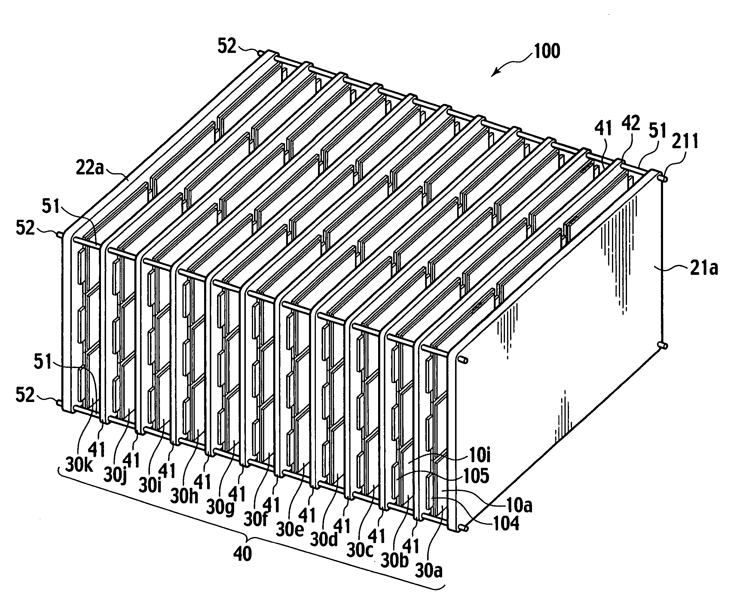
[0040] FIGS. 1 to 2B show one thin-type cell (unit cell) 10 forming a secondary battery and stacking a plurality of such thin-type cells forms a battery with a desired voltage and capacity.

[0041] More particularly, the secondary battery 10 is a flat-plate-like stack type thin battery of a lithium-family and is exemplarily comprised of three positive electrode plates 101, five separators 102, three negative electrode plates 103, a positive electrode terminal 104, a negative electrode terminal 105, an upper outer sheath member 106, a lower outer sheath member 107 and an electrolyte that is not shown. Among the...

second embodiment

[0088] Next, a battery of a second embodiment according to the present invention is described below in detail with reference to FIGS. 9A to 9D.

[0089]FIG. 9A is a plan view illustrating an upper end plate of the battery of the presently filed embodiment; FIG. 9B is a front view of the plate of the battery of the presently filed embodiment; FIG. 9C is a side view of the plate of the battery of the presently filed embodiment; FIG. 9D is a graph illustrating the degree (amount) “y” of flexure of the upper end plate of the battery of the presently filed embodiment. Incidentally, in the drawing figures, an inward direction of the battery 100 is designated by “IN” and an outward direction of the battery 100 is designated by “OUT”.

[0090] As shown in FIGS. 9A to 9C, the upper end plate 21b of the presently filed embodiment is set such that a thickness T1 at a pressing center Q is relatively thicker than a thickness T2 of an outer peripheral portion (as expressed as T1>T2).

[0091] With such...

third embodiment

[0093] Next, a battery of a third embodiment according to the present invention is described below in detail with reference to FIGS. 10A to 10D.

[0094]FIG. 10A is a plan view illustrating an upper end plate of the battery of the presently filed embodiment; FIG. 10B is a front view of the plate of the battery of the presently filed embodiment; FIG. 10C is a side view of the plate of the battery of the presently filed embodiment; and FIG. 10D is a graph illustrating the degree (amount) “y” of flexure of the upper end plate of the battery of the presently filed embodiment. Incidentally, in the drawing figures, an inward direction of the battery 100 is designated by “IN” and an outward direction of the battery 100 is designated by “OUT”.

[0095] As shown in FIGS. 10A to 10C, the upper end plate 21c is formed with a plurality of substantially “L”-shaped ribs 24, protruding upward in a direction perpendicular to a surface of the end plate 21c, which are formed on diagonal lines and substan...


PUM

PropertyMeasurementUnit
thicknessaaaaaaaaaa
rigidityaaaaaaaaaa
densityaaaaaaaaaa

Abstract

A battery is provided with a battery stack body including a plurality of stacks of secondary batteries in each of which electrode plates, stacked via a separator, are accommodated and sealed in an outer sheath member, with electrode terminals correspondingly connected to the electrode plates and extracted from an outer peripheral edge of the outer sheath member, a pair of plate-like members, stacked as outermost layers of the battery stack body, respectively, so as to be opposed to each other, and a pressing mechanism pressing the plurality of secondary batteries via the pair of plate-like members. At least one of the pair of plate-like members having a characteristic exhibiting a maximum rigidity at a pressing center determined based on a plurality of pressing points of the at least one of the pair of plate-like members that are pressed by the pressing mechanism.

Description

BACKGROUND OF THE INVENTION [0001] The present invention relates to a battery and, more particularly, to a battery that is comprised with a plurality of secondary batteries connected with one another, in each of which electrode terminals are extracted from an outer peripheral edge of an outer sheath member. [0002] Japanese Patent Application Laid-Open Publication No. 09-259859 discloses a technology wherein electrode plates are stacked via separators to form a stack body that is accommodated in an outer sheath member and a plurality of secondary batteries are stacked in a way to allow electrode terminals, connected to the electrode plates, to be extracted from an outer peripheral edge of the outer sheath member whereupon the electrode terminals, extending from the respective secondary batteries, are directly connected to by a connecting method, such as welding, to form a battery with a desired capacity and voltage. [0003] Japanese Patent Application Laid-Open Publication No. 2001-23...

Claims


Application Information

Patent Timeline
Patent Type & Authority Applications(United States)
IPC IPC(8): H01M6/42H01M10/04H01M10/05H01M10/60H01M10/613H01M10/617H01M10/635H01M10/647H01M10/651H01M10/6556H01M10/6563H01M10/6566H01M50/211
CPCH01M2/1077H01M2/1094H01M6/42H01M10/0413H01M10/0468H01M10/0525Y02E60/122H01M10/5004H01M10/5016H01M10/5032H01M10/5059H01M10/5067H01M10/0585H01M10/625H01M10/6563H01M10/647H01M10/6557H01M10/613Y02E60/10H01M50/24Y02P70/50H01M50/211
Inventor HIGASHINO, TATSUYAMURAMATSU, SATOSHI
Owner NISSAN MOTOR CO LTD
Why Eureka
Try Eureka