

Pressure sensor and related method
- Summary
- Abstract
- Description
- Claims
- Application Information
AI Technical Summary
Benefits of technology
Problems solved by technology
Method used
Image

Examples
first embodiment
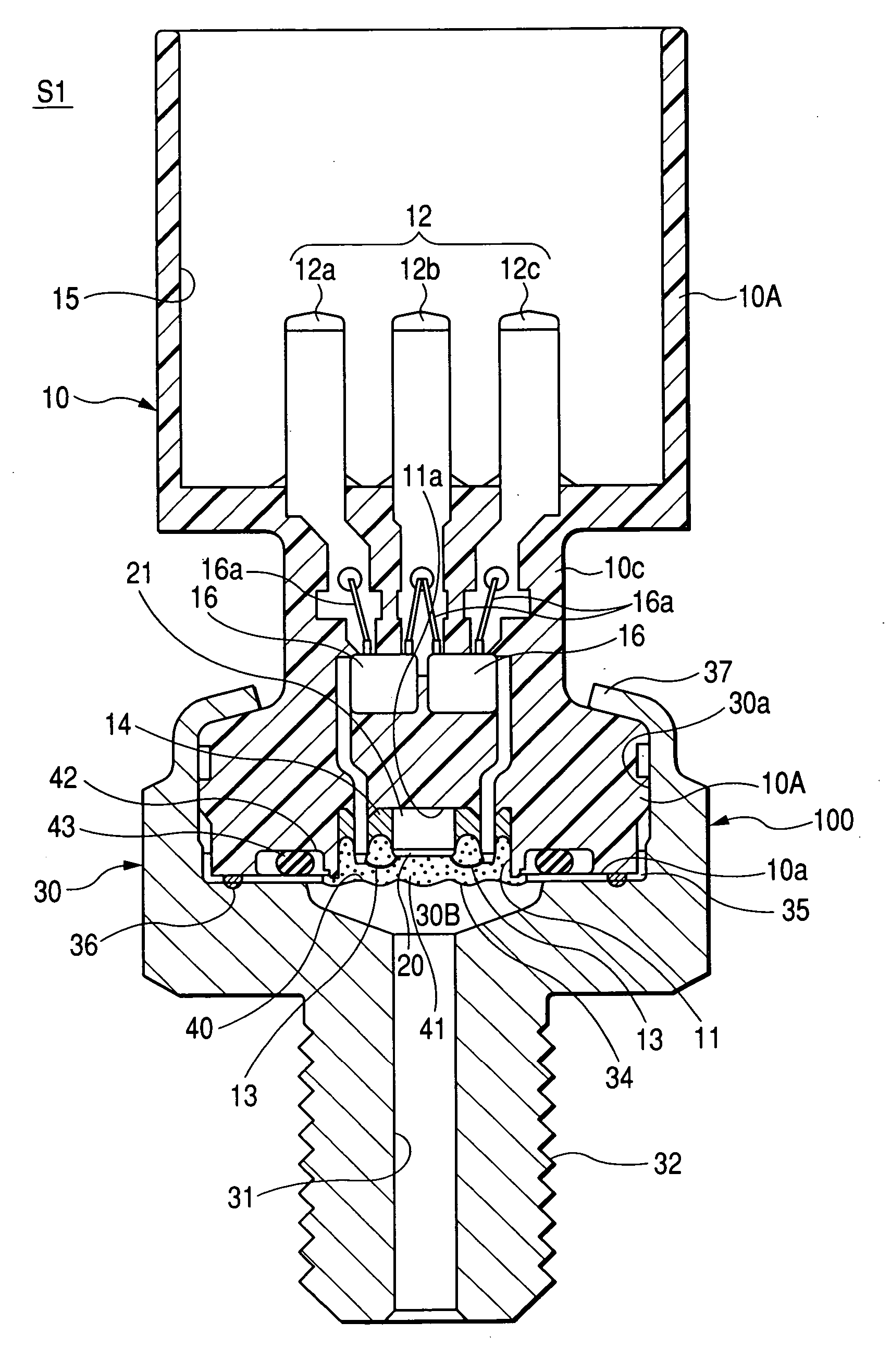
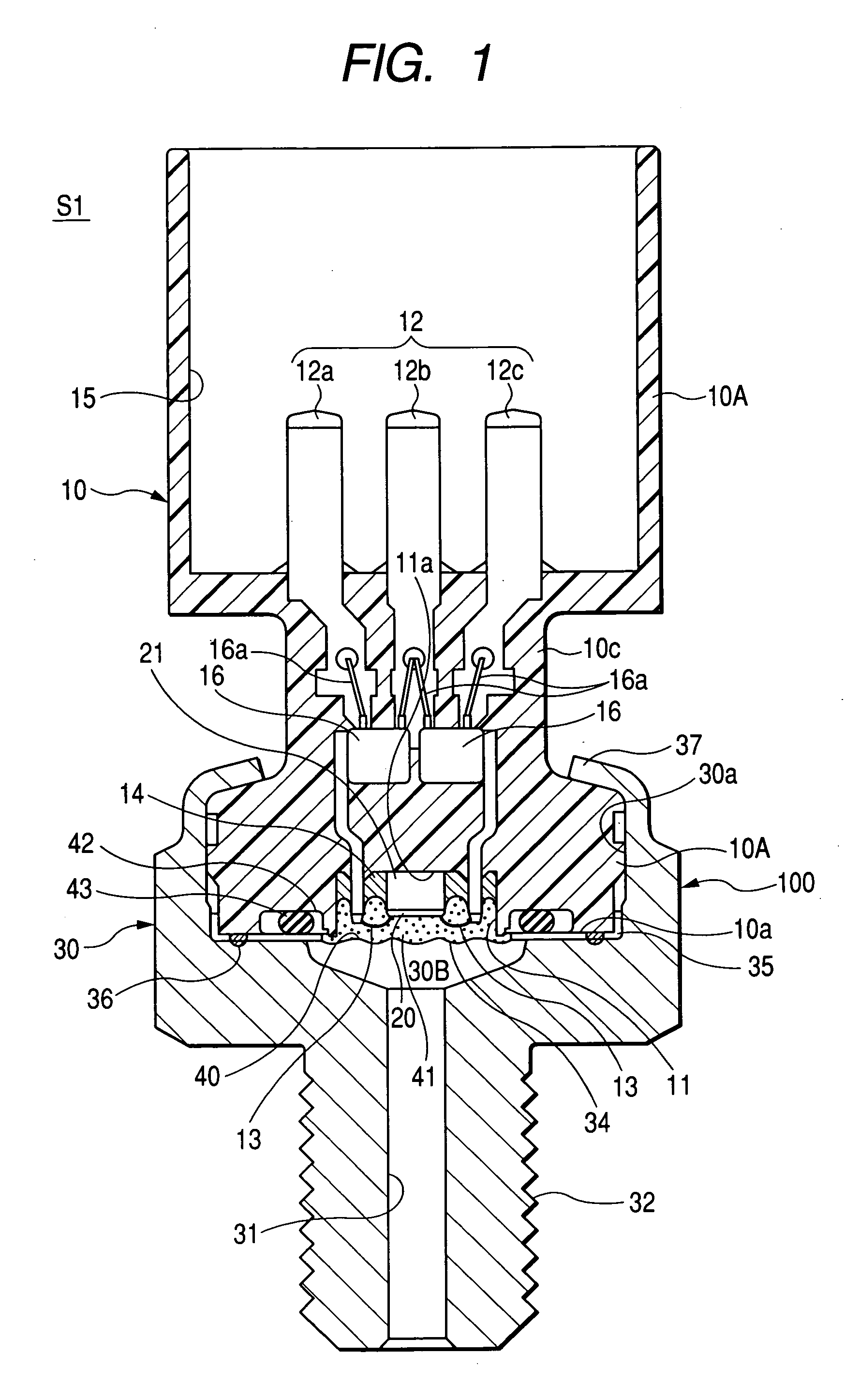
[0071] Hereinafter, a pressure sensor of an embodiment according to the present invention is described with reference to FIG. 1. FIG. 1 is a cross-sectional view of a pressure sensor S1 of the presently filed embodiment. It will be appreciated that the pressure sensor S1 is used in a location, under environments that are susceptible to electromagnetic waves, such as an engine room of a vehicle, for detecting a pressure of a combustion chamber of the engine. Also, the same component parts as those shown in FIG. 5 bear like reference numerals throughout the several views.
[0072] As shown in FIG. 1, the pressure sensor S1 is generally comprised of a casing 100 composed of a connector case 10 and a housing 30 connected to each other in a unitary structure. The housing 30 has a shoulder 30A, extending on a plane perpendicular to an axis of the housing 30, a pressure introduction bore 31, and a pressure chamber 30B defined adjacent to the shoulder 30A and communicating with the pressure i...
PUM
 Abstract
Description
Claims
Application Information