Bicycle pedal and crank apparatus

a crank and pedal technology, applied in the field of bicycles, can solve the problems of poor performance, increased cost, and more components, and achieve the effects of maximizing the stiffness to weight ratio, reducing the number of components, and reducing the cost of production

Active Publication Date: 2005-09-22
CRANK BROS INC
View PDF5 Cites 12 Cited by
  • Summary
  • Abstract
  • Description
  • Claims
  • Application Information

AI Technical Summary

Benefits of technology

[0023] This pedal and crank system has a fixed shaft that can be stronger and lighter than a spindle. With many prior art clipless pedal designs, the spindle must taper faster than preferred in order to make room for the clipping mechanism and the bearings, bushings, and seals. A fixed shaft, on the other hand, can be designed with more freedom from constraints because there is no need to fit bearings and bushings within the clipping mechanism. In fact, in many cases, the fixed shaft can be made completely hollow to maximize stiffness to weight ratio. The over-all weight of the pedal can decrease 10 to 30% or even more, depending on the pedal design. For example, the weight of the prior art four sided clipless pedal given in the above example would decrease about 20 grams per pedal for an all steel version, which is about 15%. In competitive bicycling, this is an especially large amount.
[0024] Sealed cartridge bearings are made in high volume for numerous industrial and consumer applications, and the cost is relatively low and the reliability extremely high. Sealed cartridge ball bearings have high quality seals that can seal out contamination even in the harsh conditions that some bicyclists put their bicycles through. Preferably, a sealed cartridge ball bearing such as a deep groove ball bearing is used at the end of the crank arm in order to provide adequate axial and radial loading. However, there are many other types of bearings that also work well.

Problems solved by technology

Generally, more components leads to higher costs and poorer performance in adverse environmental conditions.
Currently, because the seals are located on the pedal, they are in direct contact with the rider's shoes, which are often contaminated with dirt, mud, sand, etc.
For many pedals on the market, rebuilding the bearings and bushings is difficult or impossible for most consumers.
Oftentimes, it is very difficult to access the bearings or bushing, and once accessed, it is often difficult to remove them.
For pedals that use loose ball bearings rather than cartridge bearings or bushings, it is easy to lose the balls during disassembly, and nearly impossible to reassemble the balls and properly adjust the bearings.
Most commonly, bicyclists can suffer from knee pain and damage if the Q-factor is too large.

Method used


Image

  • Bicycle pedal and crank apparatus
  • Bicycle pedal and crank apparatus
  • Bicycle pedal and crank apparatus

Examples


Embodiment Construction

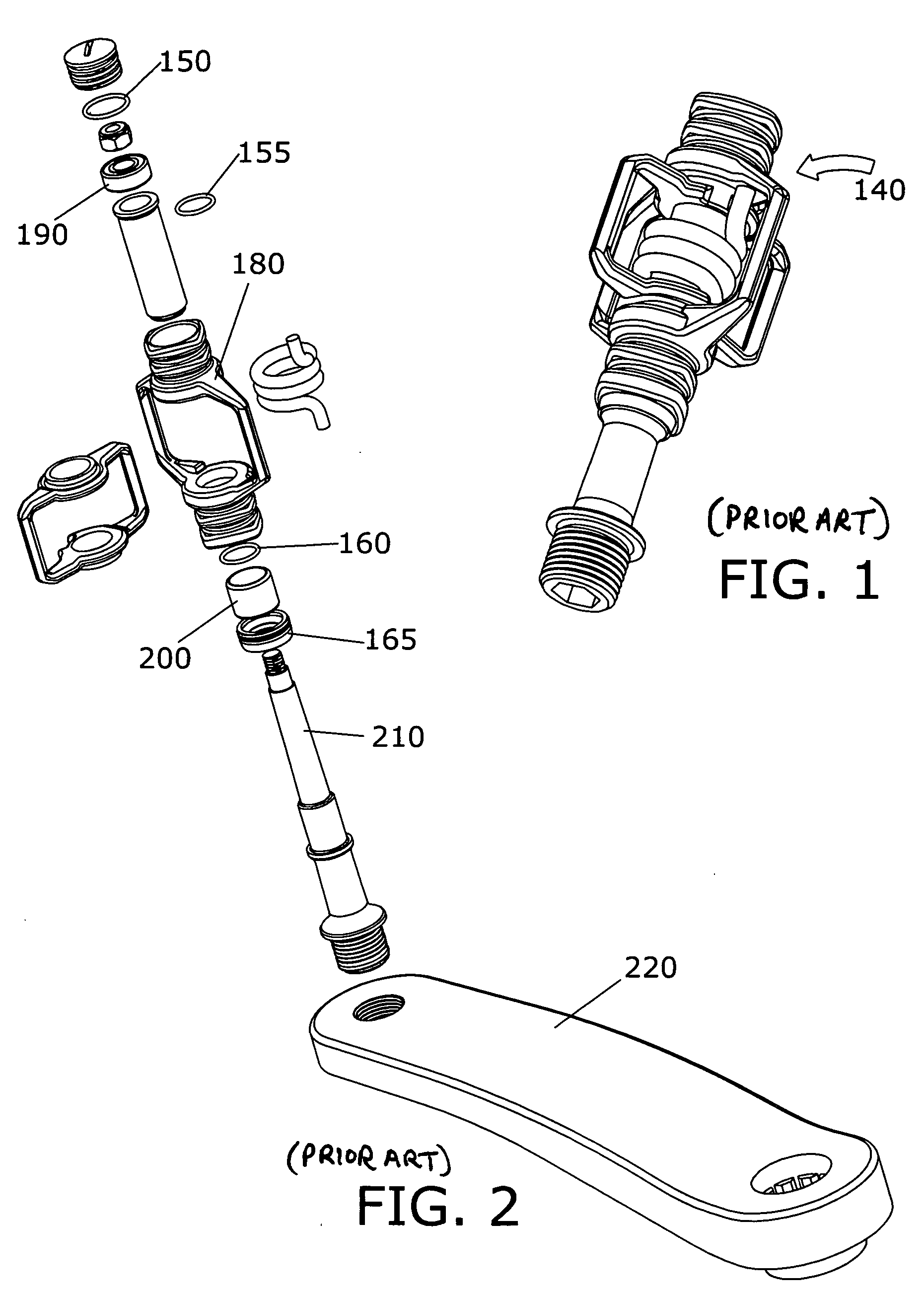
[0046]FIG. 1 shows a relatively simple prior art clipless pedal 140.

[0047]FIG. 2 shows the components of the relatively simple prior art clipless pedal 140 shown in FIG. 1. There is one static seal 150 and there are three dynamic seals 155, 160, and 165 necessary to keep contamination away from internal cartridge bearing 190 and bushing 200. Pedal 140 has only 13 components, whereas most clipless pedals have between 15 and 50 components. After spindle 210 is screwed to crank arm 220, body 180 turns in relation to crank arm 220. In other words, after assembly, spindle 210 is effectively fixed to crank arm 220, and body 180 rotates freely on bearing 190 and bushing 200. Prior art pedals, all have some form of body that rotates around a spindle. A fixed shaft in a pedal is believed to be unique.

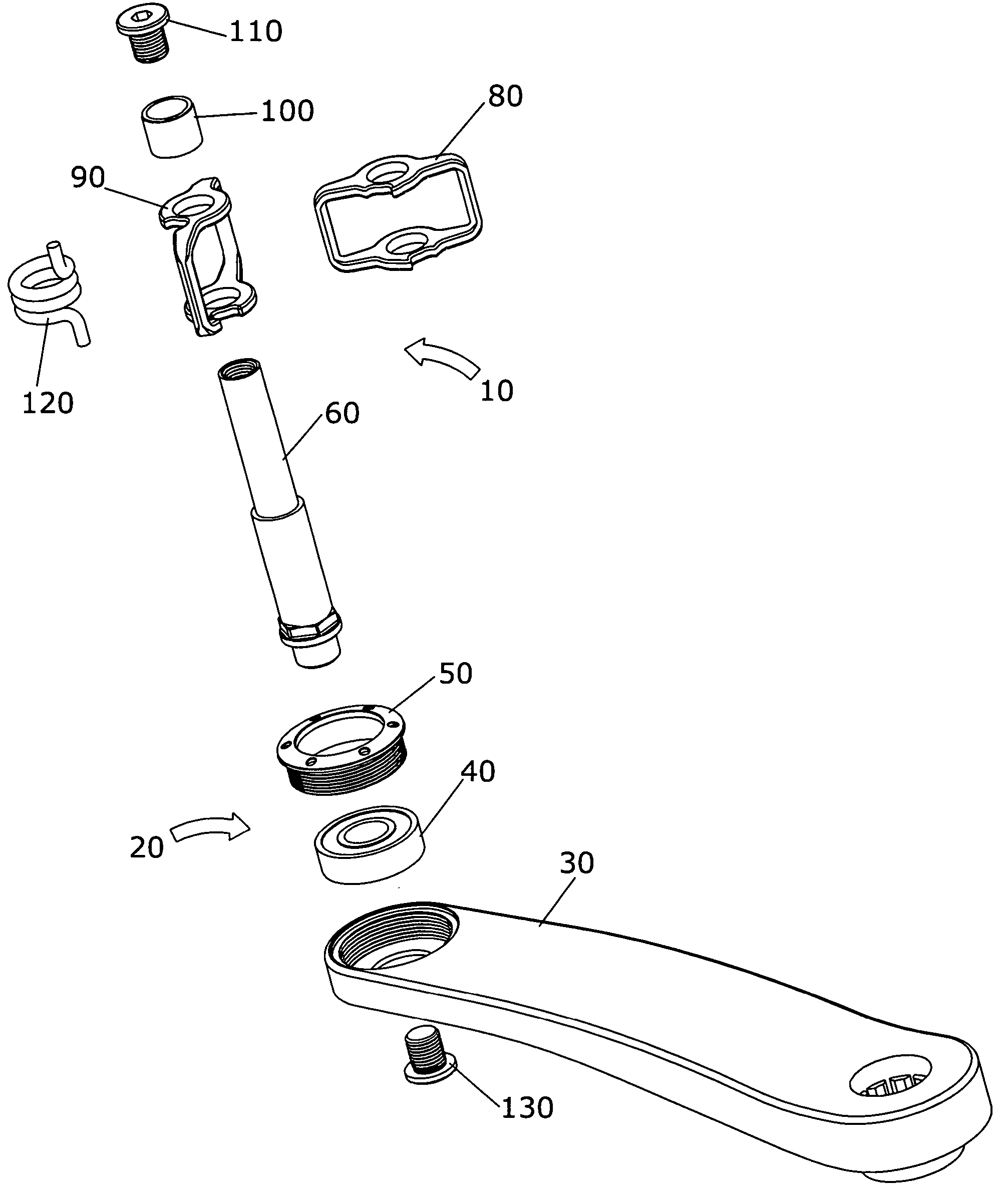
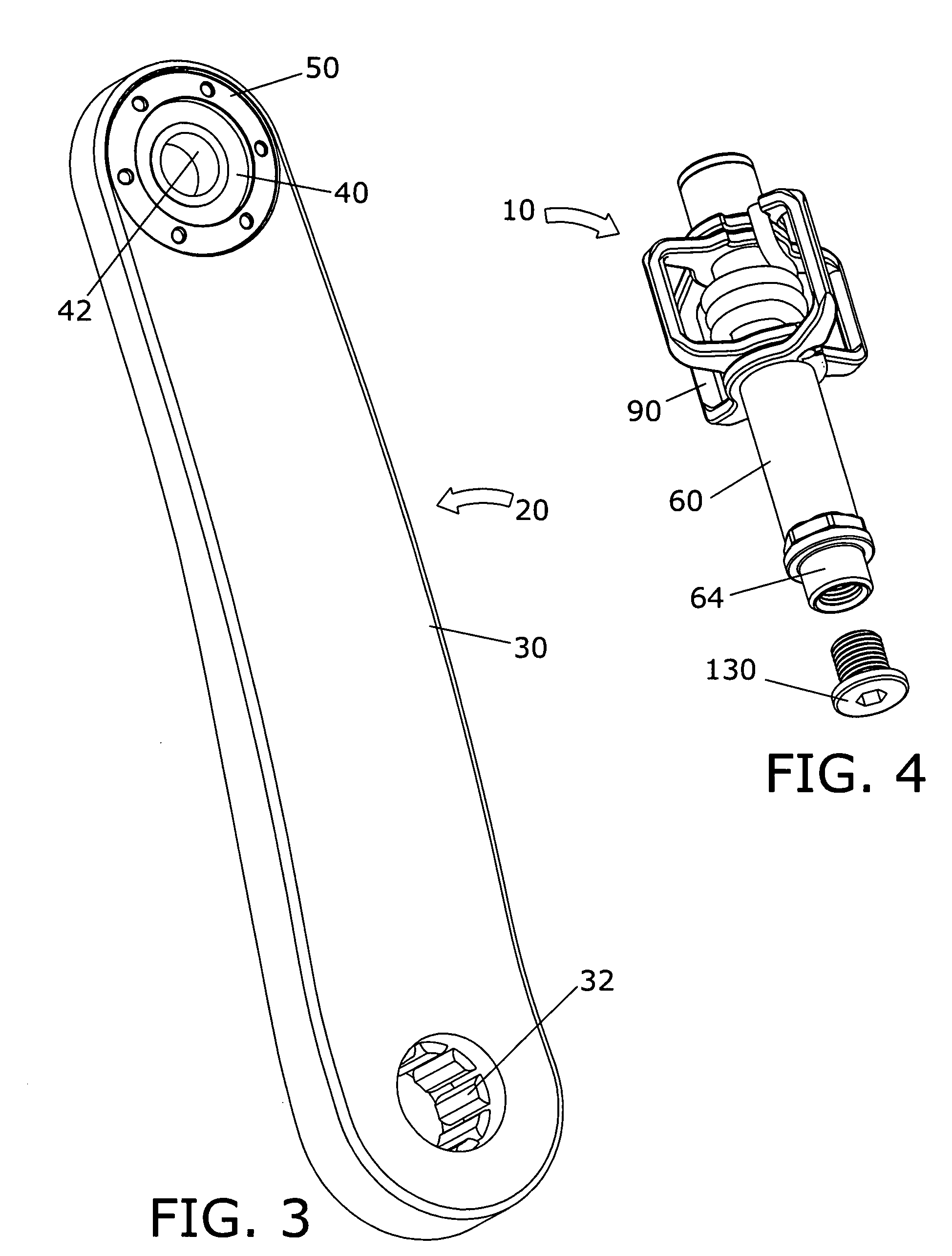
[0048] The present invention may be understood by referring to FIGS. 3-15. By way of example, referring first to FIGS. 3 to 9, it will be seen that the foregoing and other objects are attained...


PUM


Abstract

A pedal with a shaft fixed to the pedal body instead of a spindle that turns relative to the pedal body. The shaft is fixed relative to the pedal body. The pedal shaft rotates relative to the crank arm instead. A sealed cartridge ball bearing is mounted to the end of a crank arm and held in position by a retainer. The shaft is fitted through the sealed cartridge ball bearing of the crank arm and a screw secures the shaft in position. This changes the pedal to crank interface. The pedal does not require bearings or bushings or seals as with prior art pedals, because the shaft rotates within the sealed cartridge bearing held within the crank arm. The shaft and pedal body can be combined to create an even simpler pedal.

Description

BACKGROUND OF THE INVENTION [0001] 1. Field of the Invention [0002] The present invention relates generally to the field of bicycles and more particularly to an improved bicycle pedal and crank assembly. [0003] 2. Background Art [0004] A number of pedal and crank designs have been made commercially available. Pedal designs include basic pedals and a variety of clipless versions for clamping shoes to pedals. Something that all pedals have in common is that they employ a spindle that is fixedly mounted to the crank arm, a pedal body that rotates about the spindle, and bearings or bushings between the pedal body and the spindle. The pedal spindle is always rigidly connected to the crank arm, usually by threading the spindle directly into the crank arm. The pedal spindle never turns relative to the crank arm. [0005] Cranks typically have a threaded hole at the end of each crank arm for attaching the pedal spindle. Most cranks connect to a bottom bracket axle on the end of each arm oppos...

Claims


Application Information

Patent Timeline
Patent Type & Authority Applications(United States)
IPC IPC(8): B62M3/00B62M3/08G05G1/30
CPCB62M3/00Y10T74/2164Y10T74/2168B62M3/08
Inventor WINEFORDNER, CARLHERMANSEN, FRANK
Owner CRANK BROS INC
Why Eureka
Try Eureka