Method and apparatus for installing window coverings

a technology for installing window coverings and window coverings, which is applied in the direction of door/window protective devices, shutters/movable grilles, constructions, etc., can solve the problems of difficult removal of roller tube assemblies, cumbersome and time-consuming installation of each of these systems, and restricted application of heavier systems. achieve the effect of convenient removal of roller tubes

Inactive Publication Date: 2005-09-22
VRIELINK GERRIT JAN
View PDF6 Cites 39 Cited by
  • Summary
  • Abstract
  • Description
  • Claims
  • Application Information

AI Technical Summary

Benefits of technology

[0009] An apparatus according to the present invention includes a cassette to make installation of a cassette system for enclosing window coverings hardware, such as roller shade systems, quick and simple and to permit convenient removal of a roller tube from the cassette without the

Problems solved by technology

The drill-through method often leads to practical on-site complications and delays and the spring clips commonly are restricted in the load bearing capacity, and they therefore have restricted application for heavier systems.
Installation of each of these syst

Method used


Image

  • Method and apparatus for installing window coverings
  • Method and apparatus for installing window coverings
  • Method and apparatus for installing window coverings

Examples


Embodiment Construction

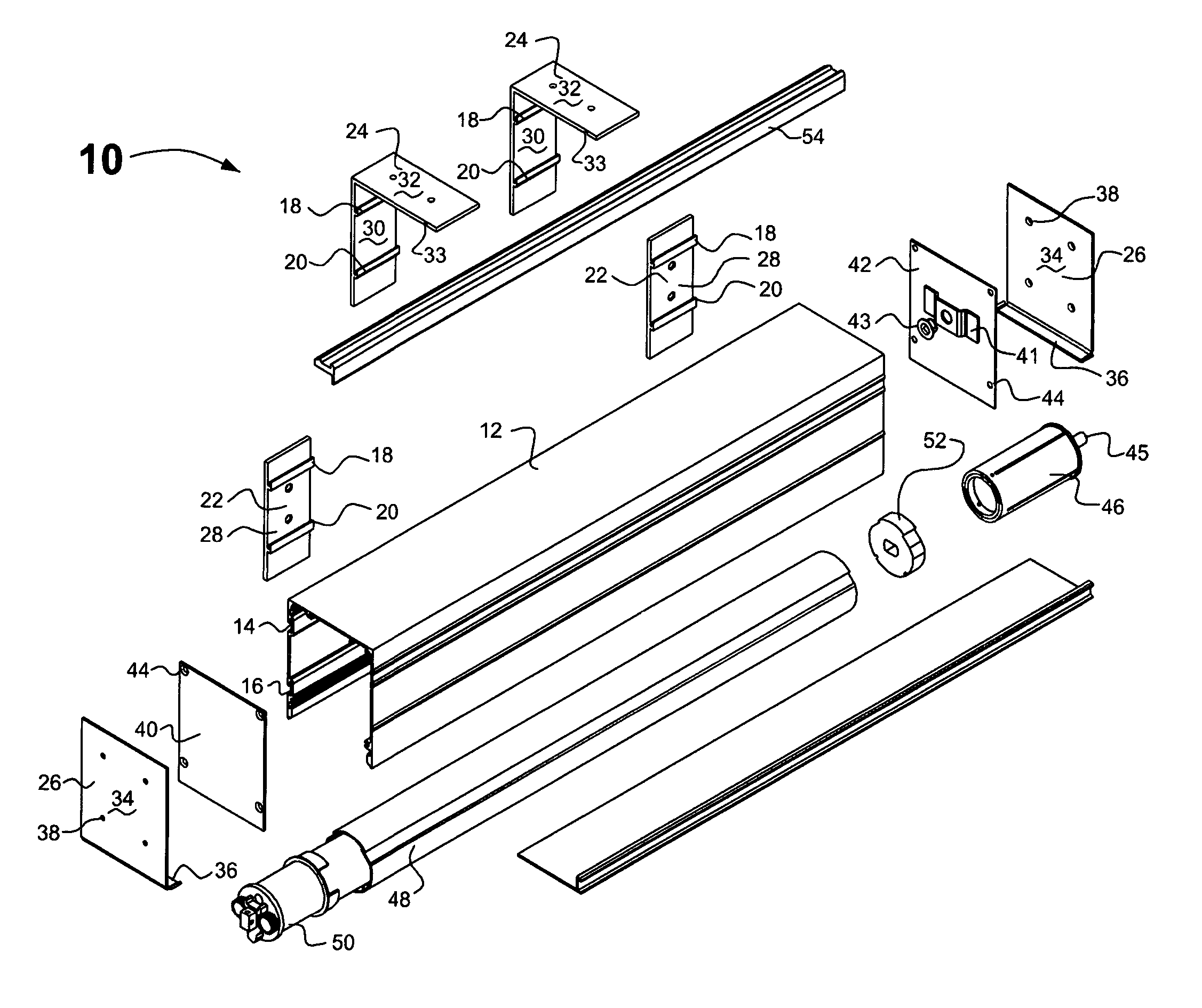
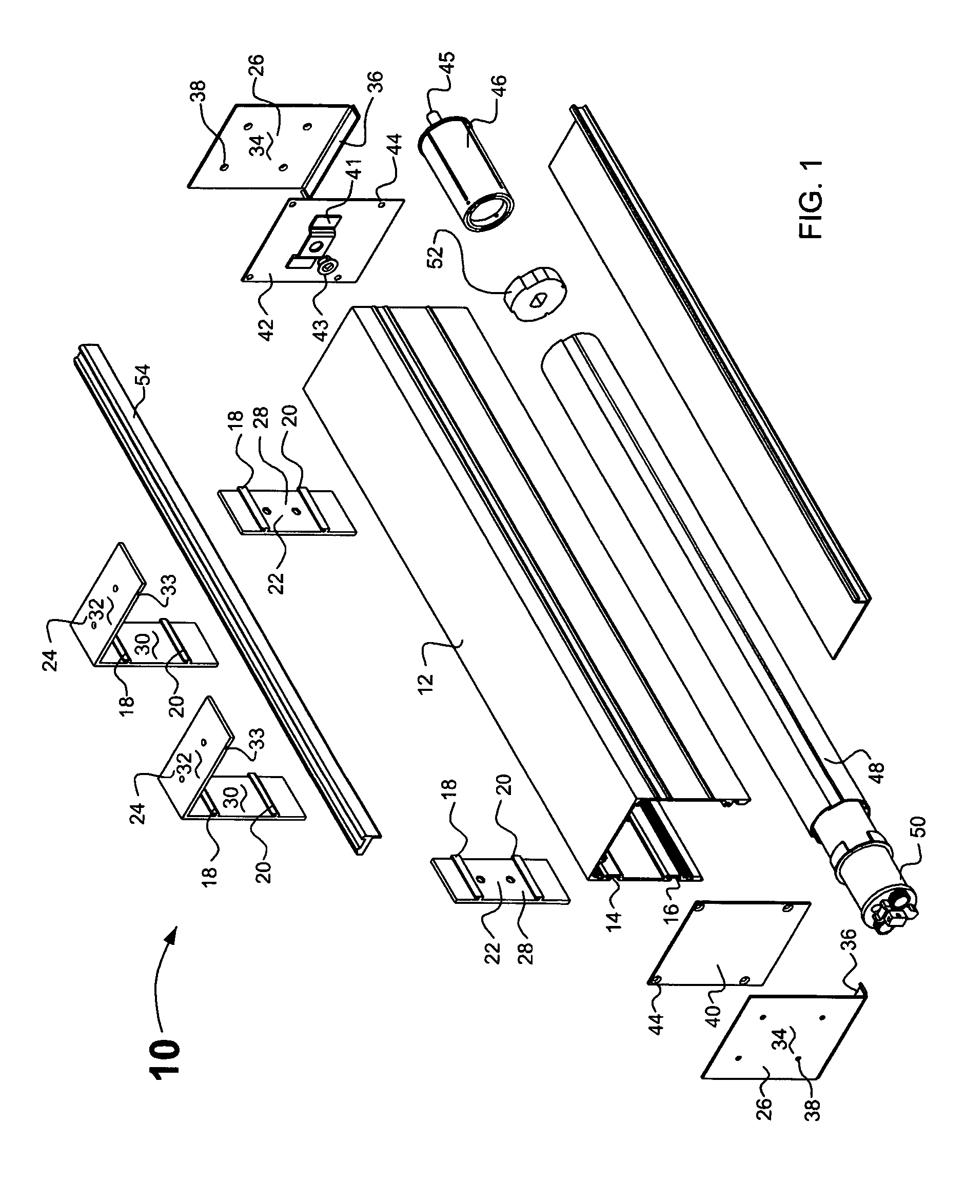
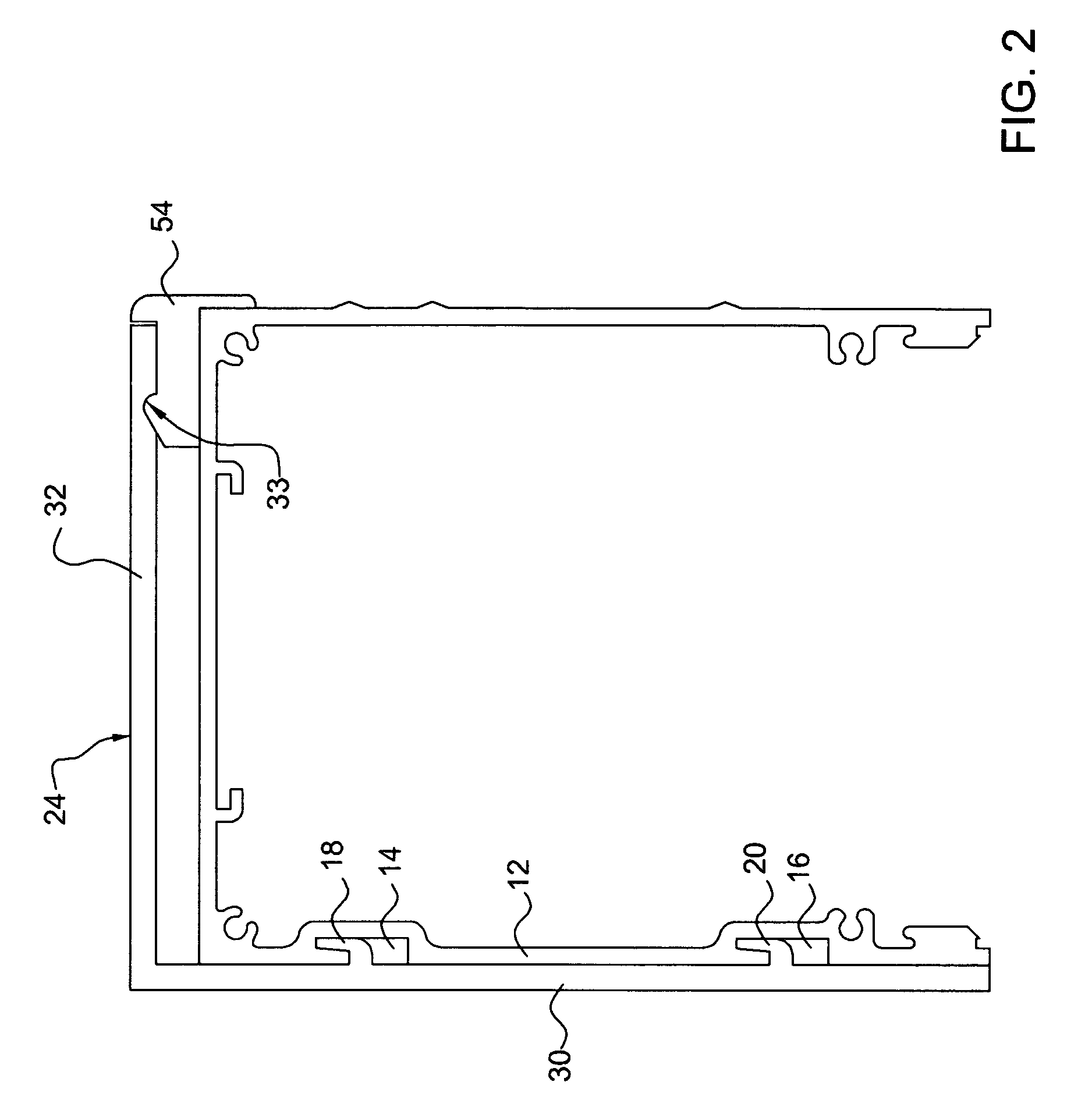
[0023] Referring now to the drawing, and in particular to FIG. 1, an apparatus according to the present invention is referred to generally by reference numeral 10. Apparatus 10 includes a square cassette 12 to make installation of a cassette system for enclosing window coverings hardware, such as roller shade systems, quick and simple and to permit convenient removal of a roller tube and shade assembly from the cassette without the need to take the cassette itself down. A cassette box is provided with two tapered slots 14 and 16 at the wall side that match with two tapered cantilevers 18 and 20 of the installation brackets. Installation of the cassette box is accomplished by simply lifting the box with its slots onto the bracket.

[0024] Brackets according to the present invention will be available as wall mount brackets 22, as ceiling mount brackets 24, and as end brackets 26 for inside mount. Referring also to FIG. 2, the wall and ceiling mount brackets feature tapered cantilevers ...


PUM


Abstract

A method and apparatus are disclosed for installation of a cassette system for enclosing window coverings hardware, such as roller shade systems and to permit convenient removal of a roller tube assembly from the cassette without the need to take down the cassette itself. A cassette box is provided with two tapered slots at the wall side that match with two tapered cantilevers of the installation brackets. Installation of the cassette box is accomplished by simply lifting the box with its slots onto the bracket. Brackets are available as wall mount brackets, as ceiling mount brackets, and as end brackets for inside mount. The wall and ceiling mount brackets feature tapered cantilevers that precisely match the tapered slots in the cassette box. The tapered shape ensures that the cassette box locks itself firmly into position and tightens itself towards the bracket. The wall brackets include a flat aluminum plate and a carrier flange that is provided with the tapered cantilevers. The bracket height corresponds exactly with the cassette height. The ceiling bracket has two flanges, the carrier flange that has exactly the same cantilever construction but is taller by the amount of the height of the cantilever, and the ceiling mount flange. The ceiling mount flange is provided with a snap-in slot that will accommodate the molding. The snap-on molding of the present invention provides a secure and easy to install aesthetic closure. The molding lock is an integral part of the ceiling bracket. The inside mount end brackets include a wall plate flange and a horizontal support flange. The wall plate flange precisely matches the cassette box end plates. This ensures full light gap closure between cassette and mounting surface. The support flange is slightly flared at front and rear to ensure a safe and stable setting for the cassette system.

Description

BACKGROUND OF THE INVENTION [0001] 1. Field of the Invention [0002] The present invention relates to the installation of roller shades and similar lift systems for window coverings inside enclosures. [0003] 2. Description of Related Art [0004] Roller or lift systems for roller shades commonly consist of a rotating tube to which the window treatment or shading material is attached. By rotating the tube the material is either raised or lowered. [0005] The drive end of the tube is provided with either a mechanical rotating clutch device or with an electric motor that activates the rotation. The opposite side of the tube is the non-drive end, which is commonly provided with a round shaft bearing to permit rotation. [0006] The common method of installation of such systems is by means of brackets that function as end supports. [0007] The enclosures currently available are either of the assembly-type where one or more plates are individually clipped onto the end brackets or they are of U-s...

Claims


Application Information

Patent Timeline
IPC IPC(8): E06B9/08E06B9/323E06B9/42E06B9/72
CPCE06B9/323E06B9/72E06B9/42
Inventor VRIELINK, GERRIT JAN
Owner VRIELINK GERRIT JAN
Why Eureka
Try Eureka