Actuator assembly

Inactive Publication Date: 2005-09-22
INTEVA PRODUCTS LLC
View PDF15 Cites 12 Cited by
  • Summary
  • Abstract
  • Description
  • Claims
  • Application Information

AI Technical Summary

Benefits of technology

[0006] An object of the present invention is to provide an actuator assembly that is less expensive and/or easier to produce. Another object of the present invent

Problems solved by technology

However, this arrangement is complicated because it includes an output lever which is separate from the worm wheel.
Furthermore, the output lever is complicated to produce and has various abutments, slots and output pins.

Method used


Image

  • Actuator assembly
  • Actuator assembly
  • Actuator assembly

Examples


Example

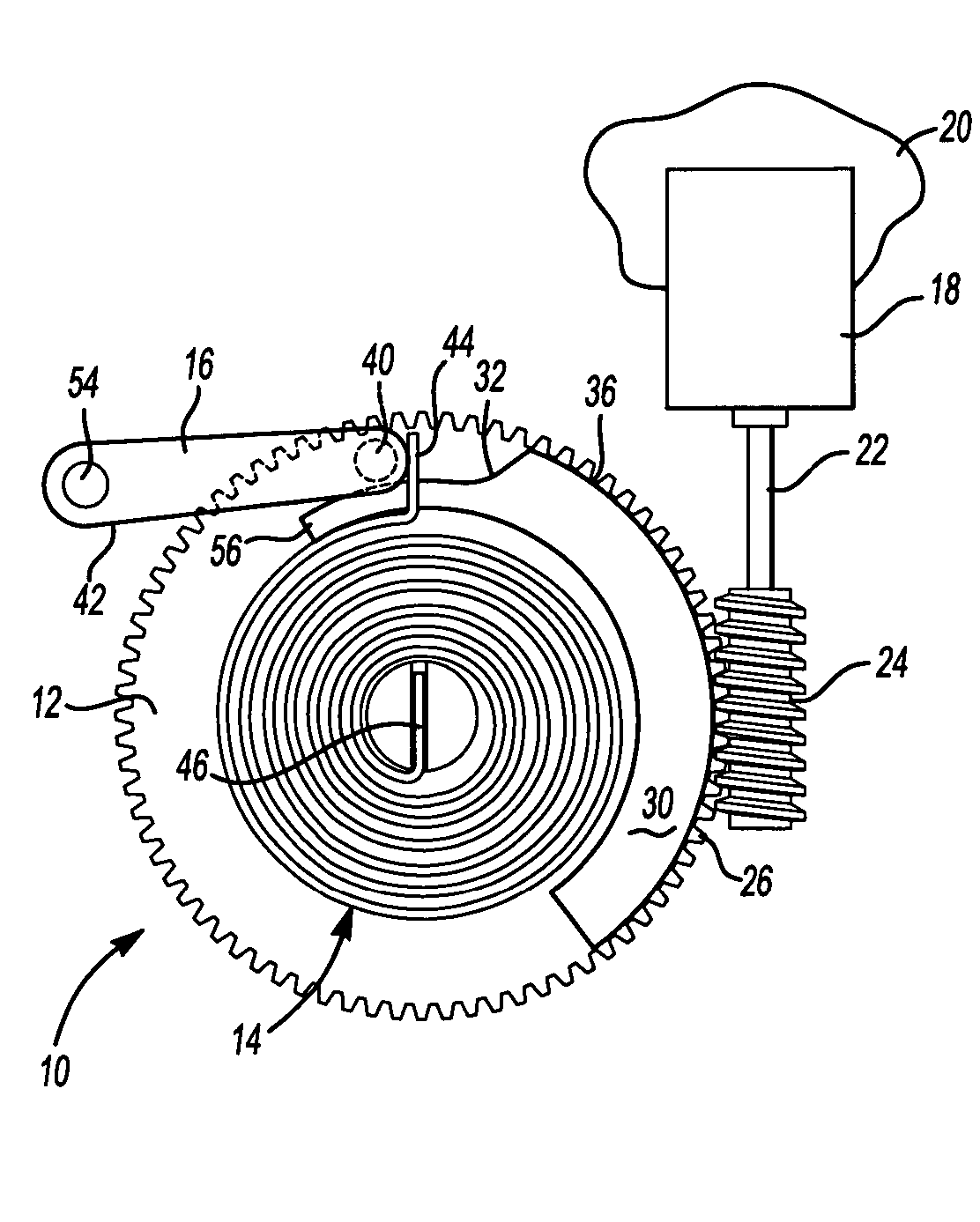
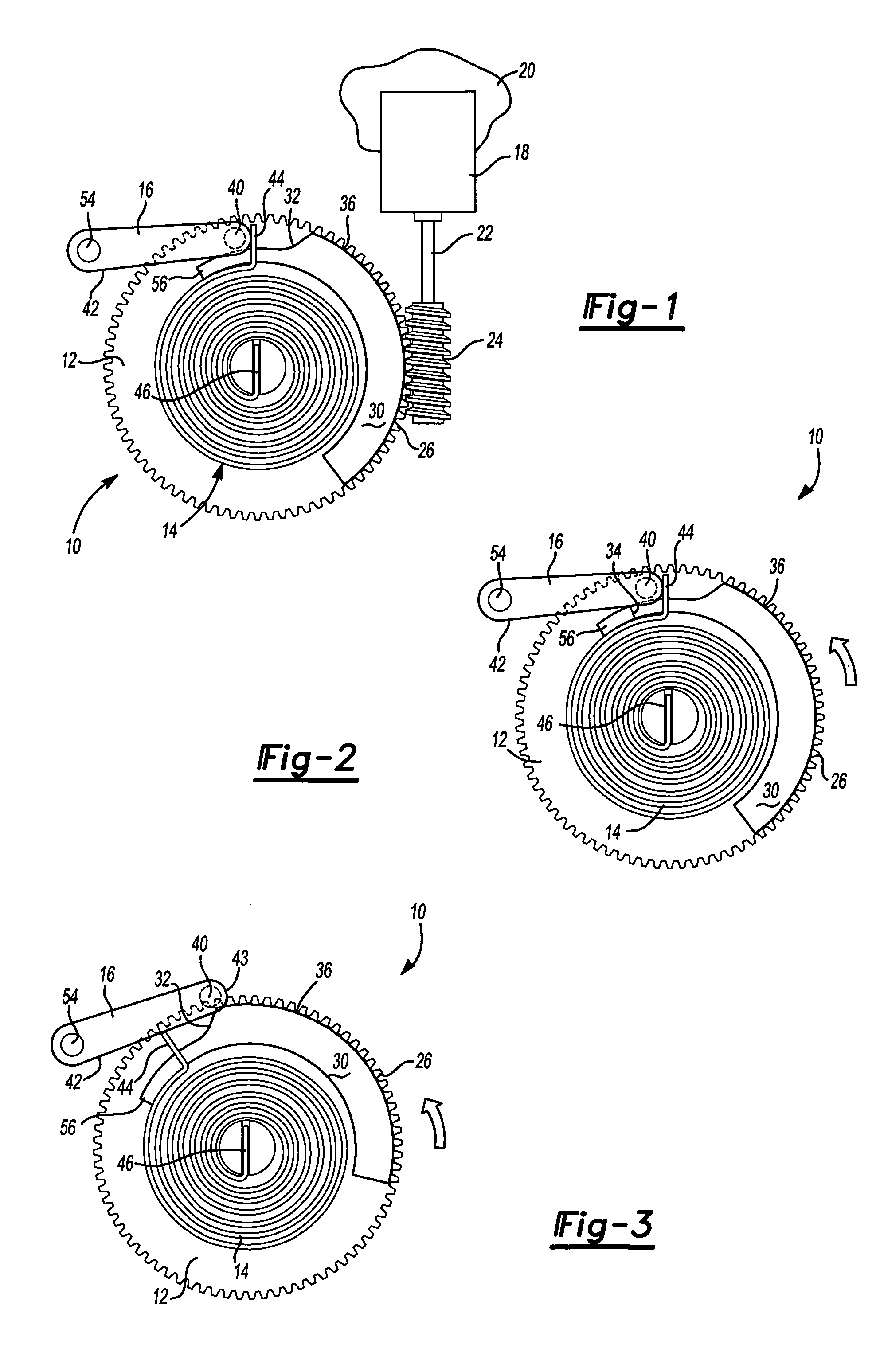
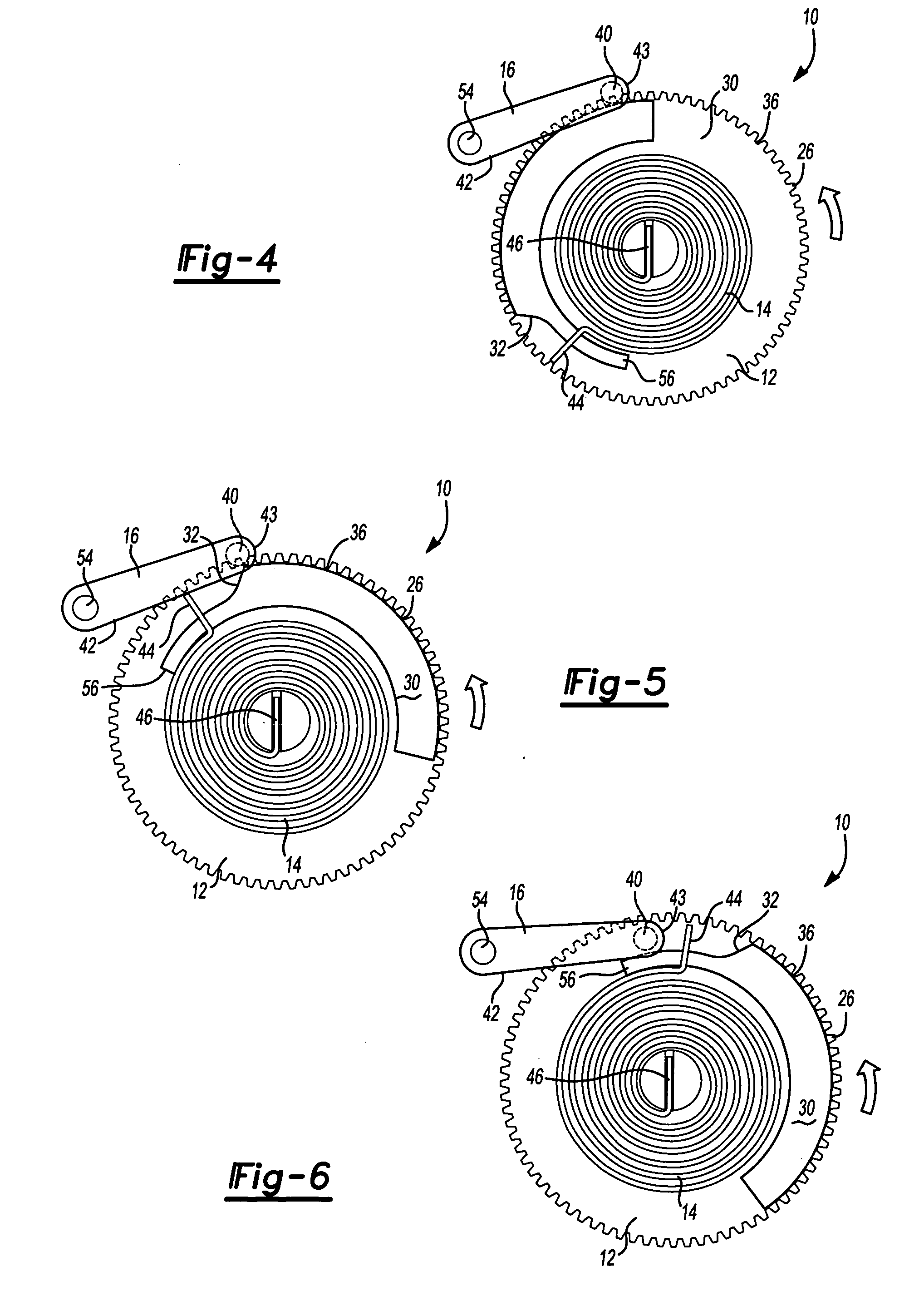
[0027]FIG. 1 shows an actuator assembly 10 including a gear wheel in the form of a worm wheel 12, an energy storage member in the form of a spiral spring 14, a detent in the form of a pawl 16, a power actuator in the form of a motor 18 (shown schematically) and an actuator assembly body 20 (only part of which is shown). The motor 18 is mounted on the actuator assembly body 20 and includes a motor shaft 22 drivingly coupled to a pinion 24. The pinion 24 drivingly engages teeth 26 (see FIG. 10) of the worm wheel 12.

[0028] The worm wheel 12 (best seen in FIGS. 7A and 10) includes a pivot 28 and a boss 30 having a camming surface 32 that are both near the worm wheel 12 and an abutment 34 and a region 56 that are both remote from the worm wheel 12. The boss 30 further includes a peripheral surface 36 which extends through an arc of approximately 120 degrees. The worm wheel 12 is pivotally mounted via the pivot 28 on the actuator assembly body 20 about an axis A which is substantially co...


PUM


Abstract

An actuator assembly includes an actuator drivingly connected to a gear wheel. The gear wheel includes an abutment secured rotationally fast having a camming surface and operable to drive an output member. The actuator assembly is operable to apply a force in a first direction to drive the output member in the first direction from a rest condition to an actuated condition and is operable to apply a force in a second direction to drive the output member in the second direction from the actuated condition to the rest condition. Movement of the output member in the second direction stores energy in the energy storage device, and movement of the output member in the first direction is assisted by the energy storage device. When the actuator assembly is in the rest condition, a detent engages the energy storage device to releasably retain the energy storage device in a rest position. Actuation of the actuator causes the camming surface to disengage the detent from the energy storage device to allow the energy storage device to assist movement of the output member in the first direction.

Description

REFERENCE TO RELATED APPLICATION [0001] This application claims priority to United Kingdom Patent Application No. GB 0405153.8 filed on Mar. 6, 2004. BACKGROUND OF THE INVENTION [0002] The present invention relates generally to an actuator assembly, in particular to an actuator assembly used with a latch assembly of a vehicle door, such as a car door. [0003] European Patent Application EP01300813 describes an actuator assembly including a spring used to assist an actuator motor when the actuator assembly is actuated. Once actuated, the actuator motor is then powered in a reverse direction to restore the actuator assembly to a rest condition, and in particular to store energy in the spring in preparation for the next actuation operation. [0004] In particular, FIG. 3 of European Patent Application EP01300813 shows a worm wheel that is driven by a motor and operates to drive a separate output lever. The output lever acts to store energy in the spring, and a stop pawl acts on an abutmen...

Claims


Application Information

Patent Timeline
IPC IPC(8): E05B65/12E05B65/20E05C3/00F03G1/00
CPCE05B81/14Y10T74/19828Y10T74/19535E05B81/25Y10T292/1047Y10T292/1082
Inventor FISHER, SIDNEY EDWARD
Owner INTEVA PRODUCTS LLC
Why Eureka
Try Eureka