
Induction heater

Active Publication Date: 2005-09-22
PANASONIC CORP
View PDF1 Cites 25 Cited by
  • Summary
  • Abstract
  • Description
  • Claims
  • Application Information

AI Technical Summary

Benefits of technology

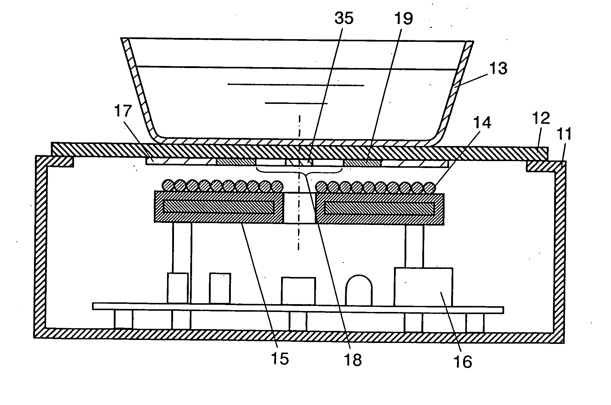
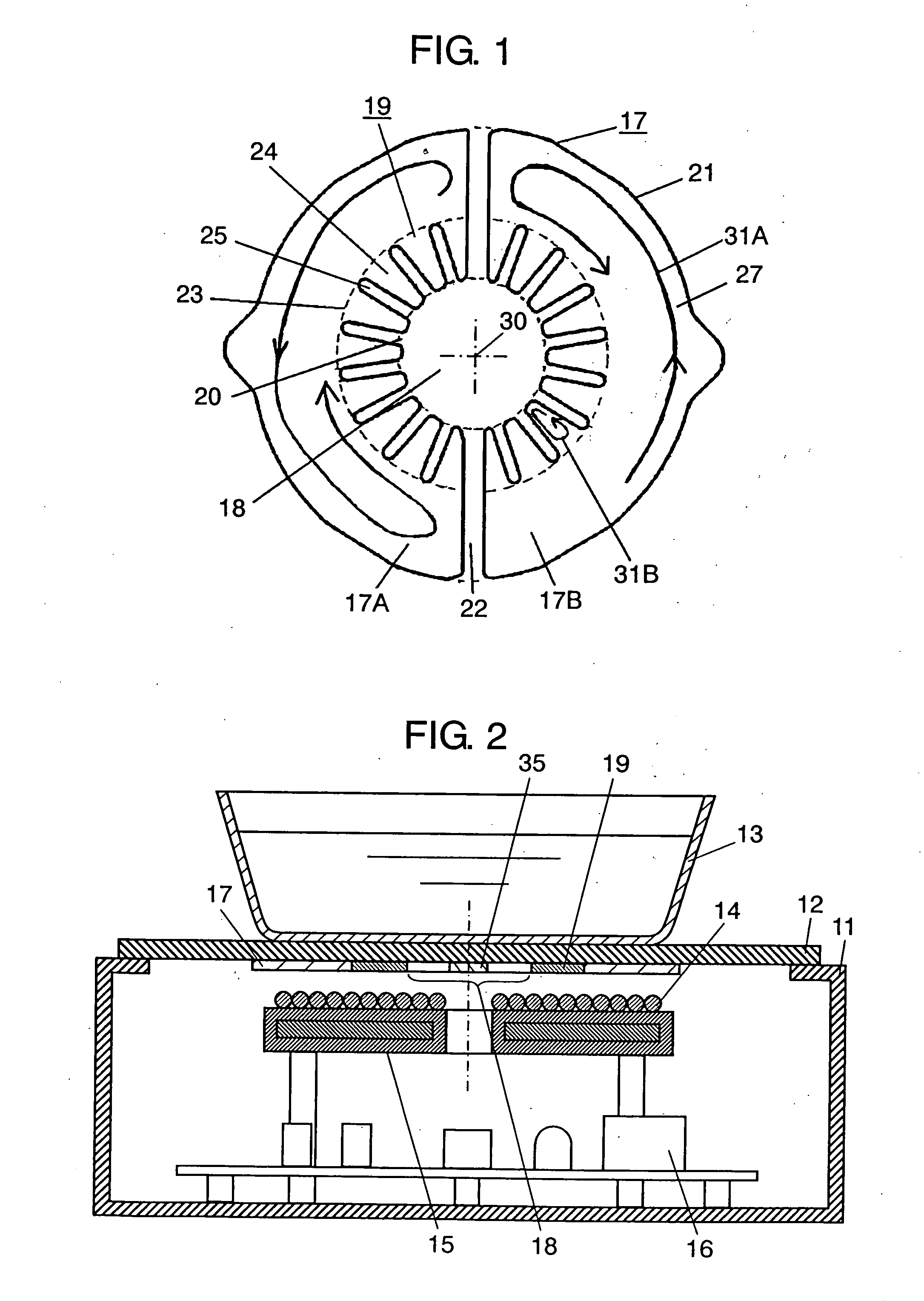
[0015] An induction heating apparatus of the present invention has a heating coil and an electric conductor. The heating coil is capable of induction-heating any utensil made of aluminum, copper and the like material having generally an equivalent or higher specific conductivity. The electric conductor is disposed between the heating coil and a utensil to be heated, and decreases a lifting force exerted on the utensil by a magnetic field generated by the heating coil. This electric conductor is disposed in a confronting manner to the heating coil, and it has an aperture in an area facing the center part of the heating coil and a slot which opens into this aperture and is isolated from an outer perimeter of the electric conductor. This structure increases the effect of the electric conductor to decrease the lifting force and improves a heating efficiency of the apparatus while preventing the electric conductor from generating excessive heat.

Problems solved by technology

Consequently, this produces a large repulsive force.
As described above, there is the possibility that utensil 3 made of aluminum floats in the air and it is not heated properly due to the lifting force exerted on utensil 3 when used for cooking on the induction cooking stove.
However, it is necessary to control a total weight of utensil 3, or the pan, and food material so that they become heavier than a prescribed weight because the floating phenomenon of utensil 3 can not be completely disregarded in the actual use.
As a result, there may be a case that it takes too much time for cooking, or the cooking is not completed because the output of coil 4 is reduced prematurely if the temperature of electric conductor 7 rises so rapidly.
For this reason, electric conductor 7 must be provided with a void area of a predetermined diameter in the center thereof, and this makes it difficult to decrease the lifting force.
However, none of the induction heating apparatuses disclosed in these inventions is provided with a heating coil capable of heating utensils made of aluminum, copper and the like materials having generally equivalent or higher specific conductivities as those.
In other words, the electric conductors disclosed in these patent publications hardly show any effect of decreasing the lifting force when induction-heating utensils made of materials having comparatively high specific resistances such as magnetic iron and stainless steel.

Method used


Image

  • Induction heater
  • Induction heater
  • Induction heater

Examples


Embodiment Construction

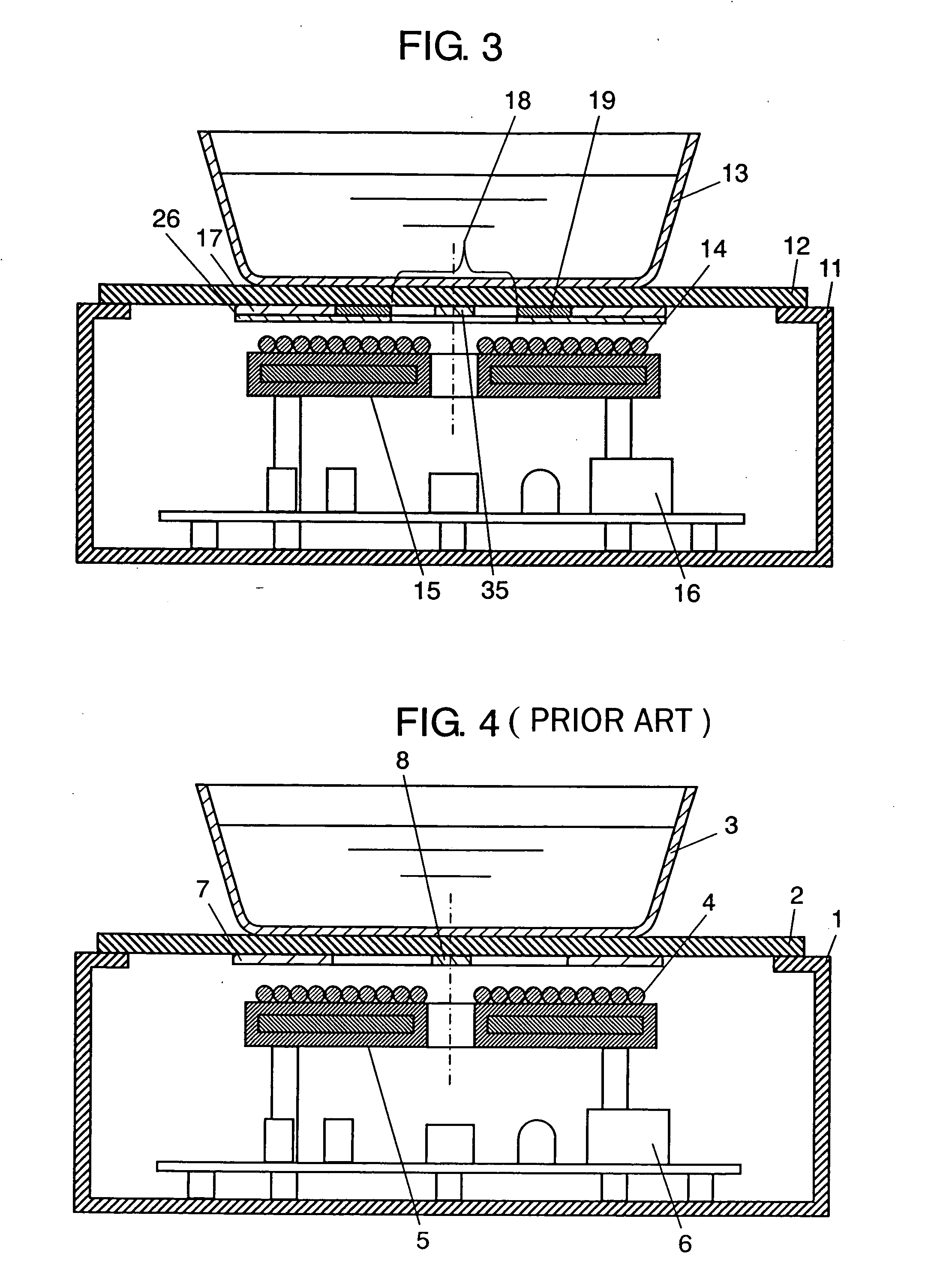
[0023]FIG. 1 is a plan view of an electric conductor in an induction heating apparatus according to an exemplary embodiment of this invention, and FIG. 2 is a cross sectional view of the same induction heating apparatus. Top plate 12 is mounted to an upper part of main body 11 that serves as an enclosure of the induction heating apparatus. Top plate 12 is constructed of an insulating material such as ceramic and crystallized glass having a thickness of 4 mm, for instance. Utensil 13 to be heated such as a pan is placed on top plate 12. Utensil 13 is made of a material of high electrical conductivity and low magnetic permeability such as aluminum, aluminum alloy, copper, copper alloy, and the like.

[0024] Induction heating unit 15 including heating coil (hereinafter referred to as “coil”) 14 is provided underneath top plate 12. Driving circuit 16 having an inverter supplies a high-frequency current of 40 kHz to 100 kHz to coil 14, which in turn generates high-frequency magnetic field...


PUM


Abstract

An electric conductor provided for decreasing a lifting force exerted on an object being heated has an aperture of a small diameter in the center thereof, which leaves a large surface area to enhance reduction of the lifting force. The electric conductor is also provided with a comb section around the aperture for preventing a circling current induced in the electric conductor from flowing into an area around the aperture. This structure can thus alleviate excessive heating around the aperture, and allow the heating coil to produce a high output power for a long duration of time even when an inwardly concaved pan is used.

Description

TECHNICAL FIELD [0001] The present invention relates to an induction heating apparatus such as an induction cooking stove for cooking food by using a pan made of a material of high electrical conductivity and low magnetic permeability such as aluminum and copper as an object to be heated. In particular, this invention relates to the induction heating apparatus that prevents the pan or the object to be heated from being lifted by the effect of high-frequency magnetic flux. BACKGROUND ART [0002] Among induction cooking stoves that produce high-frequency magnetic field with an induction heating coil for heating an object to be heated such as a pan with eddy current generated by the electromagnetic induction, there have been proposed certain types that can heat objects made of aluminum. [0003]FIG. 4 is a cross sectional view of a conventional induction cooking stove. Top plate 2 is mounted to an upper part of main body 1 that composes an enclosure of the induction cooking stove. Top pla...

Claims


Application Information

Patent Timeline
IPC IPC(8): H05B6/12
CPCH05B6/1209H05B6/12
Inventor KEISHIMA, TOSHIHIROKATAOKA, AKIRAHIROTA, IZUO
Owner PANASONIC CORP
Learn More