Pneumatic valve interface for use in microfluidic structures

Inactive Publication Date: 2005-09-22
PERKINELMER HEALTH SCIENCES INC
View PDF9 Cites 133 Cited by
  • Summary
  • Abstract
  • Description
  • Claims
  • Application Information

AI Technical Summary

Problems solved by technology

Special challenges involve mixing, dilution, fluidic circuit isolation, and anti-sediment techniques when employing microscale channels within a device.

Method used


Image

  • Pneumatic valve interface for use in microfluidic structures
  • Pneumatic valve interface for use in microfluidic structures
  • Pneumatic valve interface for use in microfluidic structures

Examples


Embodiment Construction

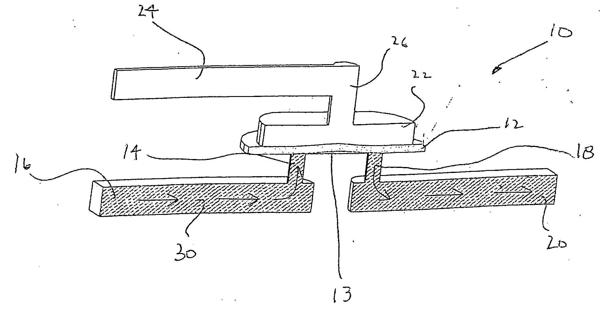
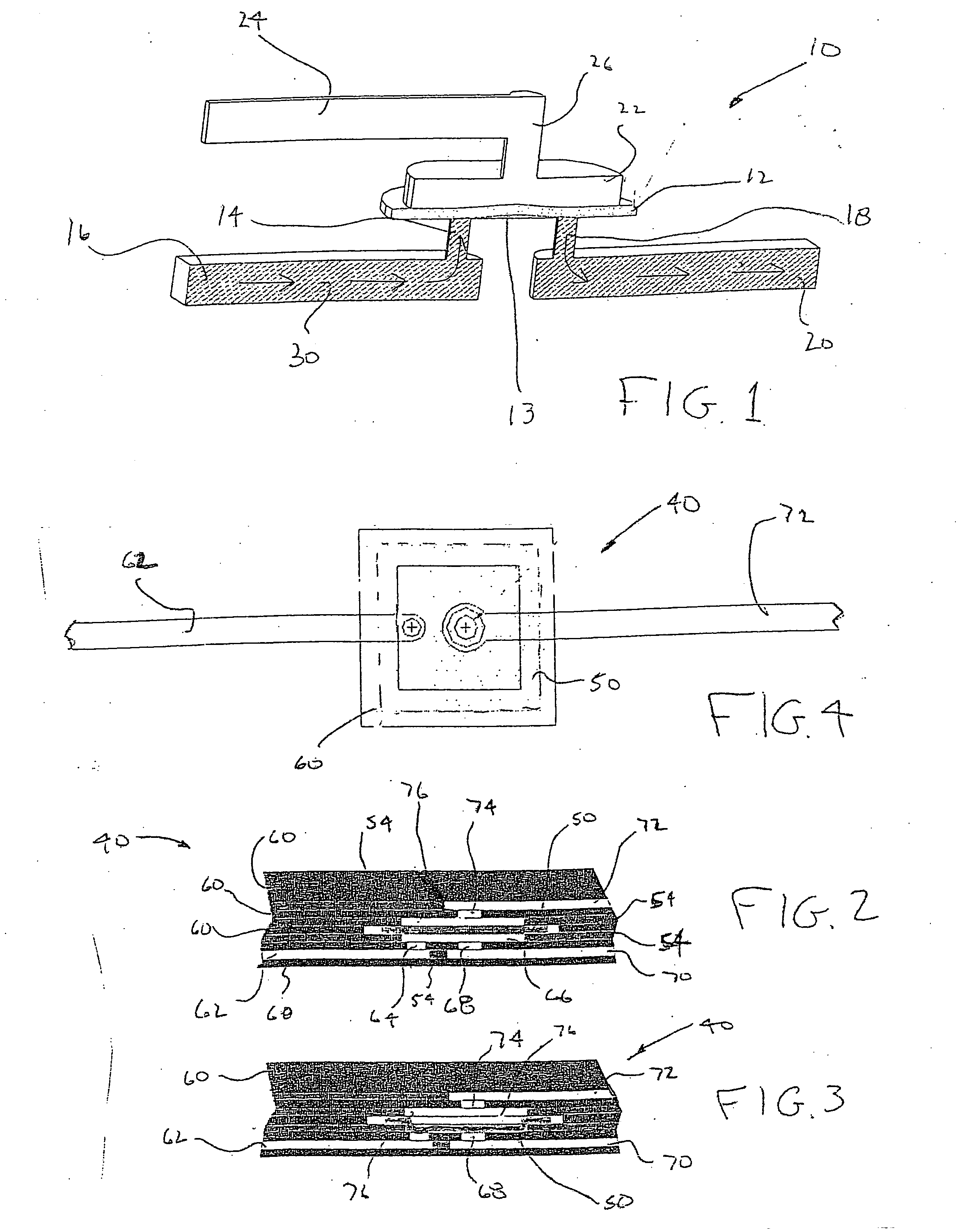
[0028] A basic zero dead volume valve according to the present invention is shown in FIG. 1. Referring now to FIG. 1, a valve generally indicated at 10 consists of a membrane layer 12 which covers a flat surface 13 coupled to an input channel 14, which is connected to a flow channel 16 and also an output channel 18 connected to a flow channel 20. Above layer 12 is an air chamber 22 which is coupled to a pneumatic source 24 by a short air channel 26. In operation, zero dead volume valve 10 works as follows: a liquid 30 enters channel 16 and travels into channel 14 where it contacts membrane layer 12. Under atmospheric conditions within air chamber 22, membrane lines flat against surface or seat 13, causing liquid 30 to stop in channel 14. However, if the fluid pressure within channel 14 exceeds the elastic force contained in membrane 13, membrane 13 will bulge out into chamber 22, allowing liquid 30 to pass under membrane 13 and flow out through channel 18 and into channel 20, as sho...


PUM

PropertyMeasurementUnit
diameteraaaaaaaaaa
air pressureaaaaaaaaaa
pressureaaaaaaaaaa

Abstract

A pneumatic valve for use in laminated plastic microfluidic structures. This zero or low dead volume valve allows flow through microfluidic channels for use in mixing, dilution, particulate suspension and other techniques necessary for flow control in analytical devices.

Description

CROSS-REFERENCE TO RELATED APPLICATIONS [0001] This patent application claims benefit from U.S. provisional Patent Application Ser. No. 60 / 281,114, filed Apr. 3, 2001, which application is incorporated herein by reference.BACKGROUND OF THE INVENTION [0002] 1. Field of the Invention [0003] This invention relates generally to microscale devices for performing analytical testing and, in particular, to a valve interface for use in laminated microfluidic structures. [0004] 2. Description of the Prior Art [0005] Microfluidic devices have recently become popular for performing analytical testing. Using tools developed by the semiconductor industry to miniaturize electronics, it has become possible to fabricate intricate fluid systems which can be inexpensively mass produced. Systems have been developed to perform a variety of analytical techniques for the acquisition of information for the medical field. [0006] Microfluidic devices may be constructed in a multi-layer laminated structure wh...

Claims


Application Information

Patent Timeline
Patent Type & Authority Applications(United States)
IPC IPC(8): G01N15/14A61M1/14B01D21/00B01L3/00F15C5/00F16K7/17F16K15/14F16K99/00G01N1/28G01N1/40G01N15/02G01N15/05G01N35/00
CPCA61M1/14Y10T436/25375B01D21/0012B01D21/283B01L3/5027B01L3/502707B01L3/50273B01L3/502738B01L3/502746B01L3/502753B01L3/502761B01L3/502776B01L2200/027B01L2200/028B01L2200/0636B01L2200/0647B01L2200/0668B01L2300/0829B01L2300/0861B01L2300/0874B01L2300/0883B01L2400/0406B01L2400/0436B01L2400/0457B01L2400/0487B01L2400/084F16K7/17F16K99/0001F16K99/0015F16K99/0025F16K99/0059F16K2099/008F16K2099/0084G01N15/0255G01N15/05G01N15/1456G01N2001/4016G01N2001/4061G01N2001/4094G01N2015/0288G01N2015/1411G01N2015/1413G01N2015/144G01N2015/1486G01N2035/00247Y10T436/2575A61M2206/11
Inventor HAYENGA, JON W.SALTSMAN, PATRICKWEIGL, BERNHARD H.
Owner PERKINELMER HEALTH SCIENCES INC
Why Eureka
Try Eureka