
Image pickup element performing image detection of high resolution and high image quality and image pickup apparatus including the same

Active Publication Date: 2005-09-22
RENESAS ELECTRONICS CORP
View PDF2 Cites 43 Cited by
  • Summary
  • Abstract
  • Description
  • Claims
  • Application Information

AI Technical Summary

Benefits of technology

[0010] The present invention has been made to solve the problem described above, and an object thereof is to provide an image pickup element capable of performing an image detection of high resolution and high image quality and an image pickup apparatus including the same, by reducing transistors per one pixel and by suppressing fixed pattern noises.
[0012] The image pickup element according to the present invention includes the first and second pixel parts each having the first and second active regions used for forming constituting components, and the first and second active regions are respectively the same in shape in the first and second pixel parts. Specifically, the active regions are the same among the pixel parts. Accordingly, the layout patterns can be uniform, and the so-called fixed pattern noises can be suppressed, whereby an image detection of high resolution and high image quality can be performed.
[0014] The image pickup apparatus according to the present invention includes a plurality of pixel parts arranged in rows and columns and each having the first and second active regions used for forming constituting components, and the first and second active regions are respectively the same in shape among the plurality of pixel parts. The plurality of pixel parts are divided into sets by two pixel parts adjacent to each other in a first direction. The adjacent sets are arranged differently relative to each other in a second direction. Accordingly, the adjacent sets are arranged in a zigzag, whereby difference in outputs due to difference in characteristics of the layout patterns can be suppressed, and eye discomfort of a user can be reduced.

Problems solved by technology

However, since the number of components for each pixel is not uniform, layout patterns are not uniform among the pixels.
In this regard, there has been such a problem that so-called fixed pattern noises (hereinafter also referred to as FPN) occur greatly with nonuniform layout patterns, which prevent an image detection of high resolution and high image quality.

Method used


Image

  • Image pickup element performing image detection of high resolution and high image quality and image pickup apparatus including the same
  • Image pickup element performing image detection of high resolution and high image quality and image pickup apparatus including the same
  • Image pickup element performing image detection of high resolution and high image quality and image pickup apparatus including the same

Examples


first embodiment

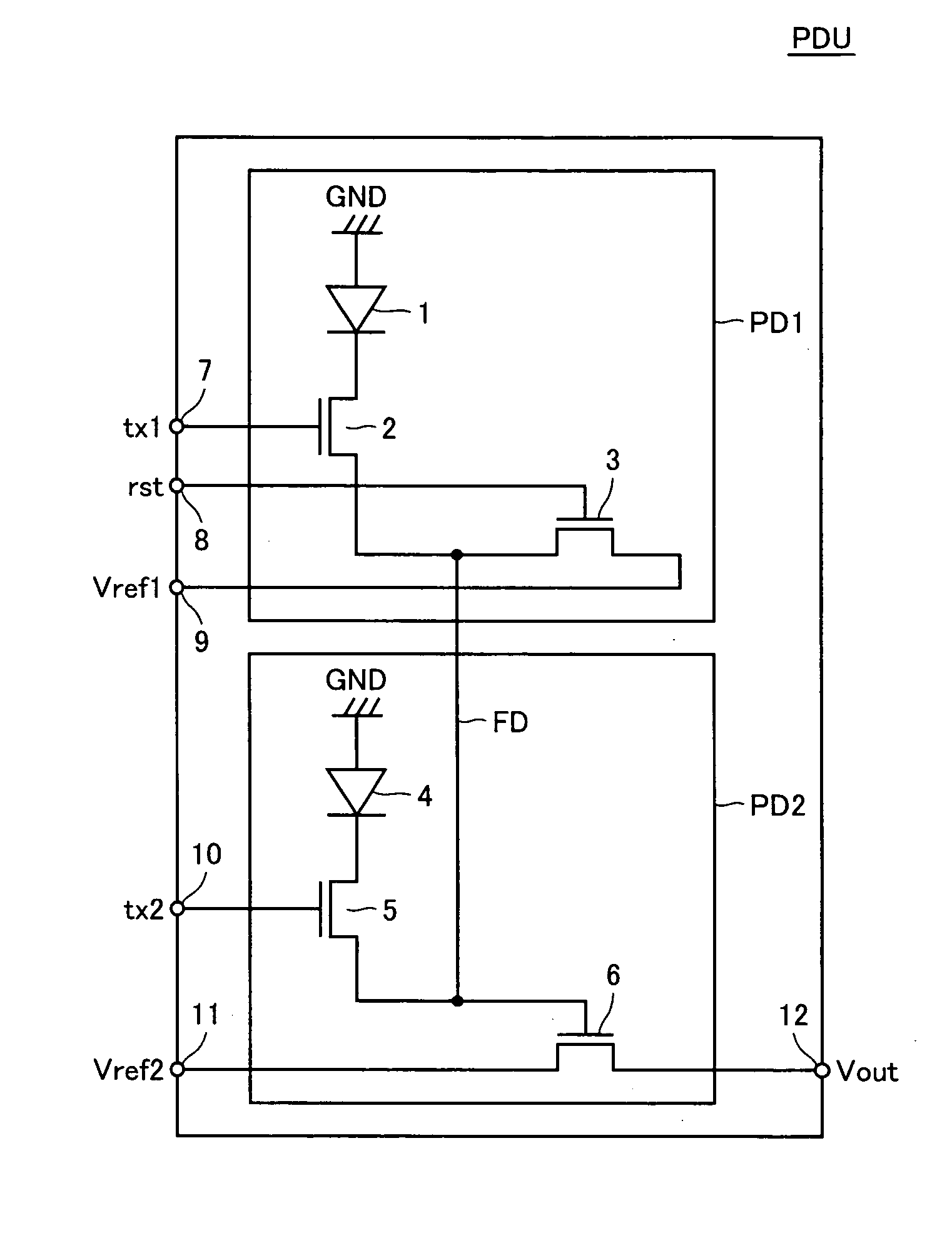
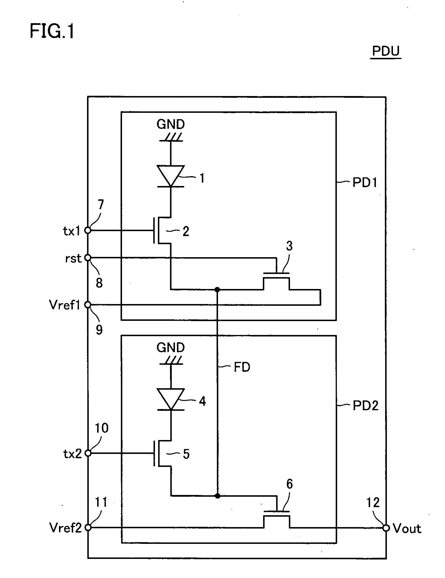
[0026] Referring to FIG. 1, an image pickup unit PDU according to a first embodiment is formed by two pixel parts PD1, PD2.

[0027] Pixel part PD1 includes a photodiode 1 having a photoelectric conversion function, a transferring transistor 2 transmitting photocarriers accumulated in photodiode 1 to a floating diffusion FD, and a resetting transistor 3 for resetting a potential of floating diffusion FD.

[0028] Pixel part PD2 includes a photodiode 4 having a photoelectric conversion function, a transferring transistor 5 transmitting photocarriers accumulated in photodiode 4 to floating diffusion FD, and an amplifying transistor for amplifying a signal transmitted to floating diffusion FD and outputting the amplified signal. Pixel parts PD1 and PD2 are electrically coupled to each other by floating diffusion FD.

[0029] Photodiode 1 and transferring transistor 2 are serially connected between fixed voltage GND and floating diffusion FD. Transferring transistor 2 has its gate electricall...

second embodiment

[0062] Referring to FIG. 5, image pickup unit PDU arranged on an array ARY according to a second embodiment of the present invention is described.

[0063]FIG. 5 shows array ARY having a plurality of pixel parts PD arranged in rows and columns, a horizontal scanning circuit 50 for outputting control signals tx and rst and control voltage Vref and the like to control image pickup unit PDU, a vertical scanning+reading controlling circuit 60 for selecting an output signal via read lines from image pickup unit PDU and for reading a data signal, and constant current sources 20 for controlling voltage levels of read lines in data reading.

[0064] In array ARY, a plurality of pixel parts PD are arranged as image pickup units PDU, each being a set of two adjacent pixel parts PD arranged in a first direction that is the vertical direction. Pixel parts PD in each image pickup unit PDU are the same as that described in the first embodiment, and therefore detailed description thereof is not repeat...


PUM


Abstract

In a pixel part, in a first active region, a photodiode and a transferring transistor are formed. In a second active region, a resetting transistor is formed. In a pixel part, in a first active region, a photodiode and a transferring transistor are formed. In a second active region, an amplifying transistor is formed. The first and second active regions are respectively the same in shape in image pixel parts. The resetting transistor and the amplifying transistor are shared by the pixel parts.

Description

BACKGROUND OF THE INVENTION [0001] 1. Field of the Invention [0002] The present invention relates to an image pickup element having a photoelectric conversion function and an image pickup apparatus including the same. [0003] 2. Description of the Background Art [0004] Conventionally, image pickup elements having photoelectric conversion function are used as image sensors since they can be arranged one or two dimensionally to obtain image signals, and they find wide application such as video cameras, copy machines, facsimile machines and the like. [0005] Among such image pickup elements, there are CMOS sensors manufactured through processes compatible with production of MOS (Metal Oxide Semiconductor) transistors of high integration density. [0006] In recent years, particularly reduction of image pickup elements in size has been required, and various schemes for achieving a higher integration have been proposed. [0007] In Japanese Patent Laying-Open Nos. 2001-24948 and 2002-50752, sc...

Claims


Application Information

Patent Timeline
IPC IPC(8): H01L27/146H01L27/14H01L31/113H04N5/335H04N5/365H04N5/369H04N5/374H04N5/3745
CPCH01L27/14603H01L27/14609H01L27/14641H01L27/14645H01L27/14621H01L27/146
Inventor HARA, KUNIHIKOKUBO, HIROSHIENDO, YASUYUKIKIMURA, MASATOSHI
Owner RENESAS ELECTRONICS CORP
Learn More