Electrical machine

Inactive Publication Date: 2005-09-22
ABB POWER GRIDS SWITZERLAND AG
View PDF7 Cites 0 Cited by
  • Summary
  • Abstract
  • Description
  • Claims
  • Application Information

AI Technical Summary

Benefits of technology

[0019] By providing a field-equalizing member in the form of windings, it is possible to avoid electrical flashover when connecting a cable to the machine.
[0020] By using a solid insulating material, it is possible to have a considerably

Problems solved by technology

One disadvantage of these prior art insulating layers is that they have to be made thick to function satisfactorily.
Another disadvantage of handling such layers is that it entails a risk of contamination.
In many cases there is a relative shortage of space at the locations where a transformer is to be placed.
However, because of the size of the transformers, there is a risk that they may blow down, which results in costs as well as maintenance and repair work.
However, it is

Method used


Image

  • Electrical machine
  • Electrical machine
  • Electrical machine

Examples


Example

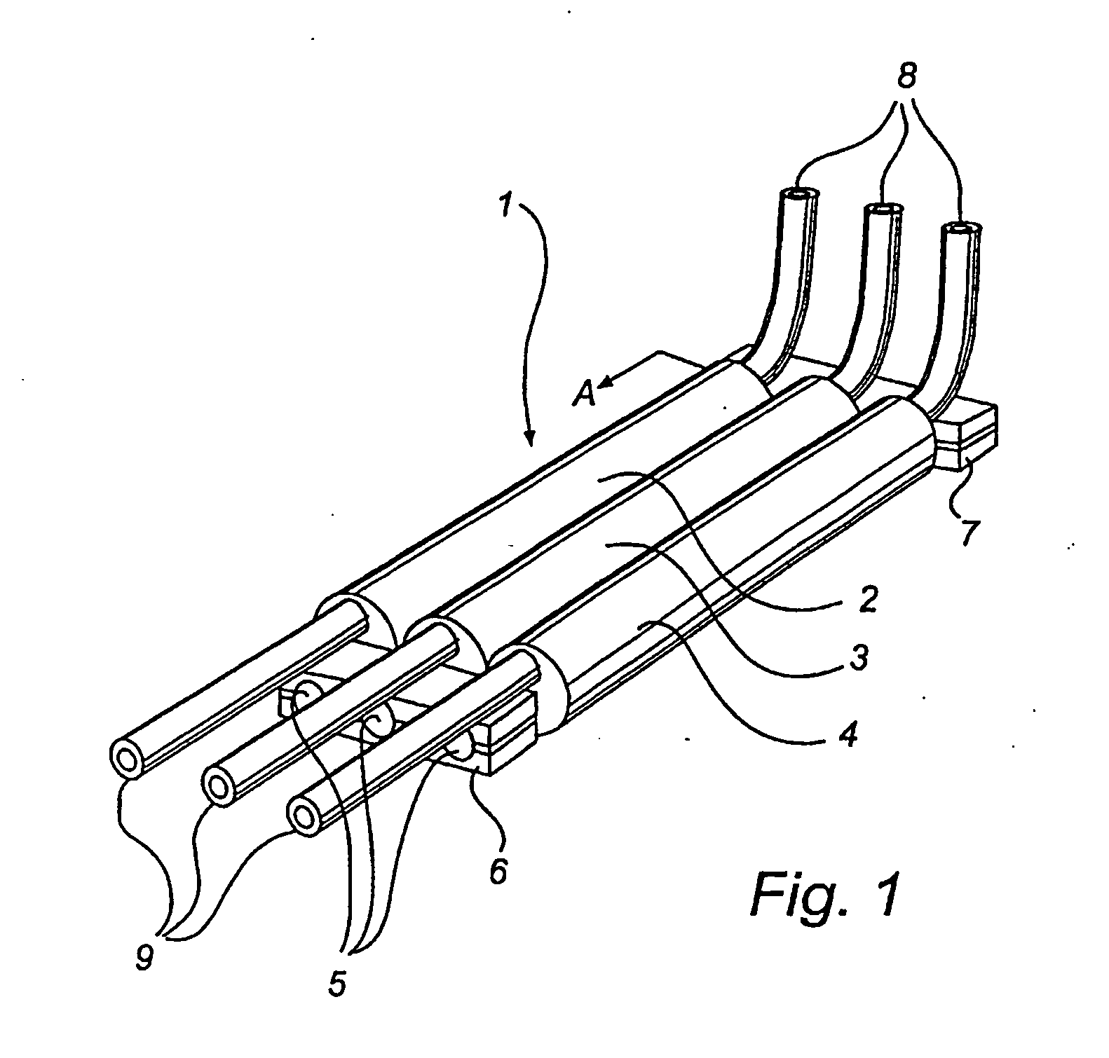
[0072]FIG. 1 shows an electrical machine according to a preferred embodiment of the present invention in the form of a three-phase transformer 1 comprising three single-phase transformers 2, 3, 4. The cores 5 of the single-phase transformers are connected to yokes 6, 7 at both ends. High-voltage cables 9 are connected to high-voltage windings in the single-phase transformers and low-voltage cables 8 are connected to low-voltage windings in the single-phase transformers. The transformer in FIG. 1 is considerably more elongated than conventional transformers and may therefore be located in long and narrow spaces, such as cable channels and the like.

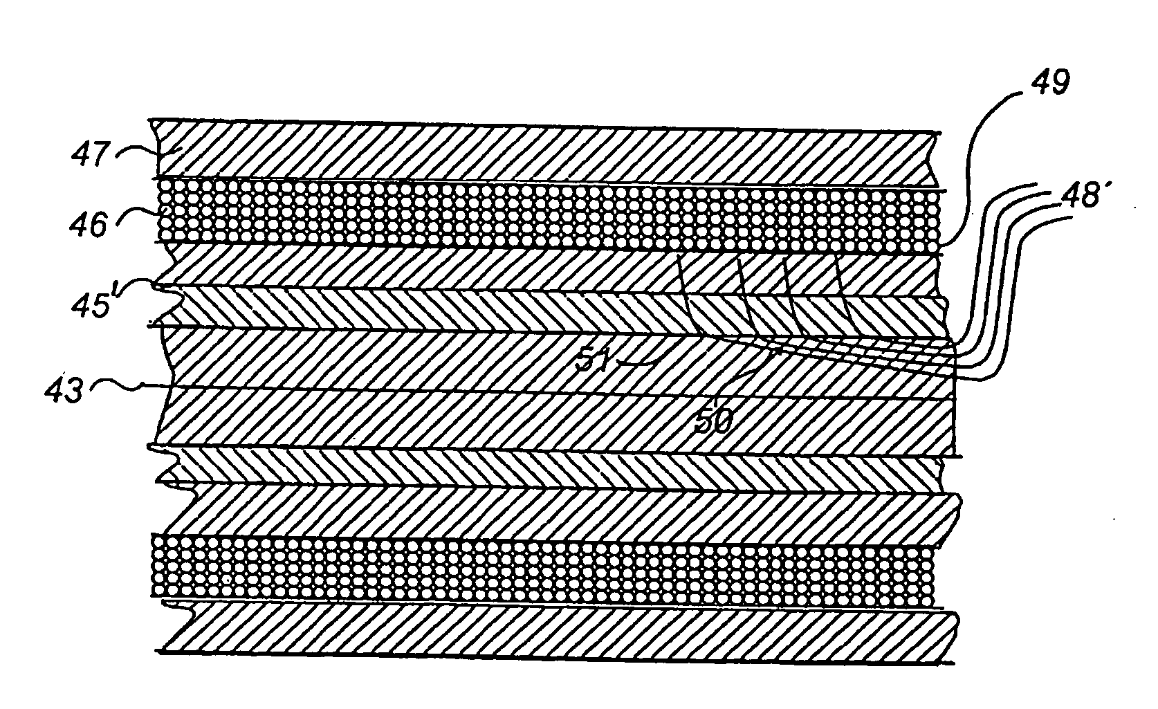
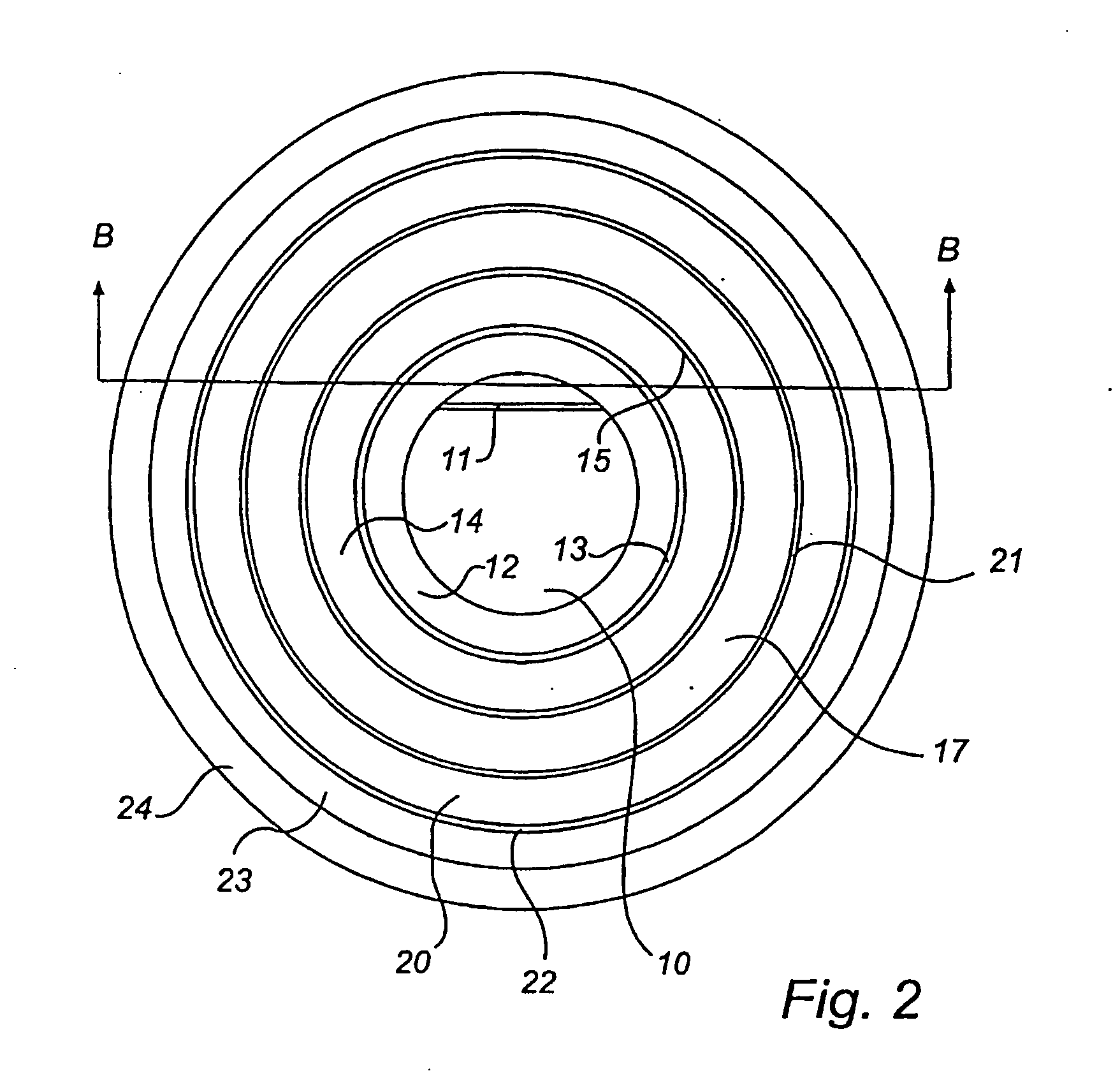
[0073]FIG. 2 shows a cross section of one of the single-phase transformers 2, 3, 4 at A in FIG. 1. FIG. 3 shows a cross section of the same single-phase transformer at B in FIG. 2. The transformer is a high-voltage transformer operating under a square voltage. The single-phase transformer comprises an iron core 10 that is built up of a plu...


PUM


Abstract

An electric machine comprises a core (10) of magnetic material and a first insulating layer (14) of a solid electrically insulating material surrounding the core. A high-voltage winding (17) in the form of an electric conductor is wound around a first part (16) of the first insulating layer and a field-equalizing member (19) is arranged around a second part (18) of the first insulating layer. Further, a second insulating layer (20) of a solid electrically insulating material surrounds the high-voltage winding and the field-equalizing member. The field-equalizing member comprises at least one first sub-member in the form of a winding (27, 28, 37, 38), and an electric cable conductor (31) is intended to be connected to the high-voltage winding at the field-equalizing member.

Description

TECHNICAL FIELD [0001] The present invention relates to an electrical machine comprising a core of a magnetic material and a high-voltage winding in the form of an electric conductor wound around a first part of the core. The present invention also relates to use of an electrical machine according to the above. BACKGROUND OF THE INVENTION [0002] Electrical machines comprising a high-voltage winding are used to a large extent in various applications in networks for transmission and distribution of electricity. Examples of non-rotating machines of this kind are transformers and reactors. [0003] High voltage in this context means voltages in excess of 1 kV. [0004] In addition to comprising a high-voltage winding, known transformers also comprise a low-voltage winding, and conventionally the high-voltage winding and the low-voltage winding are arranged around a core of magnetic material. Further, insulating layers are arranged at least between the core and one of the windings and also b...

Claims


Application Information

Patent Timeline
IPC IPC(8): H01F27/08H01F27/32H01F27/34
CPCH01F27/085H01F27/34H01F27/324
Inventor VALDEMARSSON, STEFAN
Owner ABB POWER GRIDS SWITZERLAND AG
Why Eureka
Try Eureka