
Active night vision with adaptive imaging

a technology of night vision and adaptive imaging, applied in the field of night vision systems, can solve the problems of generating non-intuitive images that can be difficult to interpret, affecting vehicle styling, and generating large amounts of energy generated by bulbs, etc., to achieve the effect of reducing system costs and complexity, being inexpensive, and being versatil

Inactive Publication Date: 2005-09-22
FORD GLOBAL TECH LLC
View PDF3 Cites 22 Cited by
  • Summary
  • Abstract
  • Description
  • Claims
  • Application Information

AI Technical Summary

Benefits of technology

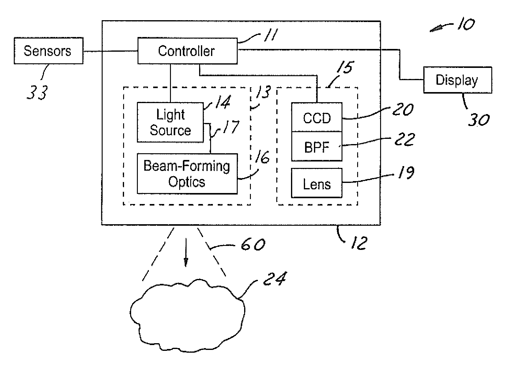
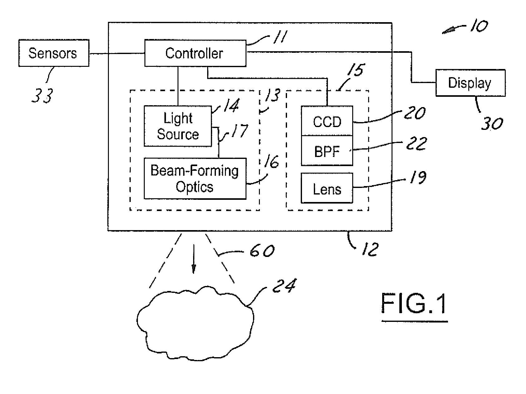
[0013] The embodiments of the present invention provide several advantages. One advantage that is provided by several embodiments of the present invention is the provision of utilizing a single fixed receiver to generate adaptive image signals. In so doing the present invention minimizes system costs and complexity. In this regard, the present invention provides an active night vision system that is inexpensive, versatile, and robust.

Problems solved by technology

Externally mounted cameras can negatively affect vehicle styling.
Far-infrared cameras are also costly to manufacture and generate non-intuitive images that can be difficult to interpret.
Filtering a significant portion of the energy generated from a bulb is expensive, energy inefficient, and generates undesired heat.
Also, filter positioning is limited in incandescent applications, since the filter must be located proximate an associated light source.
As well, multiple incandescent sources are often required to provide requisite illumination, thus increasing complexity and costs.
If the field of view is set too wide, it makes identifying distant objects difficult, particularly at high speeds.
If it is set too narrow, it can lack appropriate coverage at low vehicle speeds or while turning the vehicle.
Such mechanical controls, however, increase system complexity and, resultantly, system cost and potential warranty claims.

Method used


Image

  • Active night vision with adaptive imaging
  • Active night vision with adaptive imaging
  • Active night vision with adaptive imaging

Examples


Embodiment Construction

[0022] In the following figures the same reference numerals will be used to refer to the same components. While the present invention is described with respect to an adaptive imaging active night vision system, the present invention may be applied in various applications where near infrared imaging is desired, such as in adaptive cruise control applications, in collision avoidance and countermeasure systems, and in image processing systems. The present invention may be applied in various types and styles of vehicles as well as in non-vehicle applications.

[0023] In the following description, various operating parameters and components are described for one constructed embodiment. These specific parameters and components are included as examples and are not meant to be limiting.

[0024] Additionally, in the following description the term “near infrared light” refers to light having wavelengths within the 750 to 1000 nm spectral region. The term also at least includes the spectrum of l...


PUM


Abstract

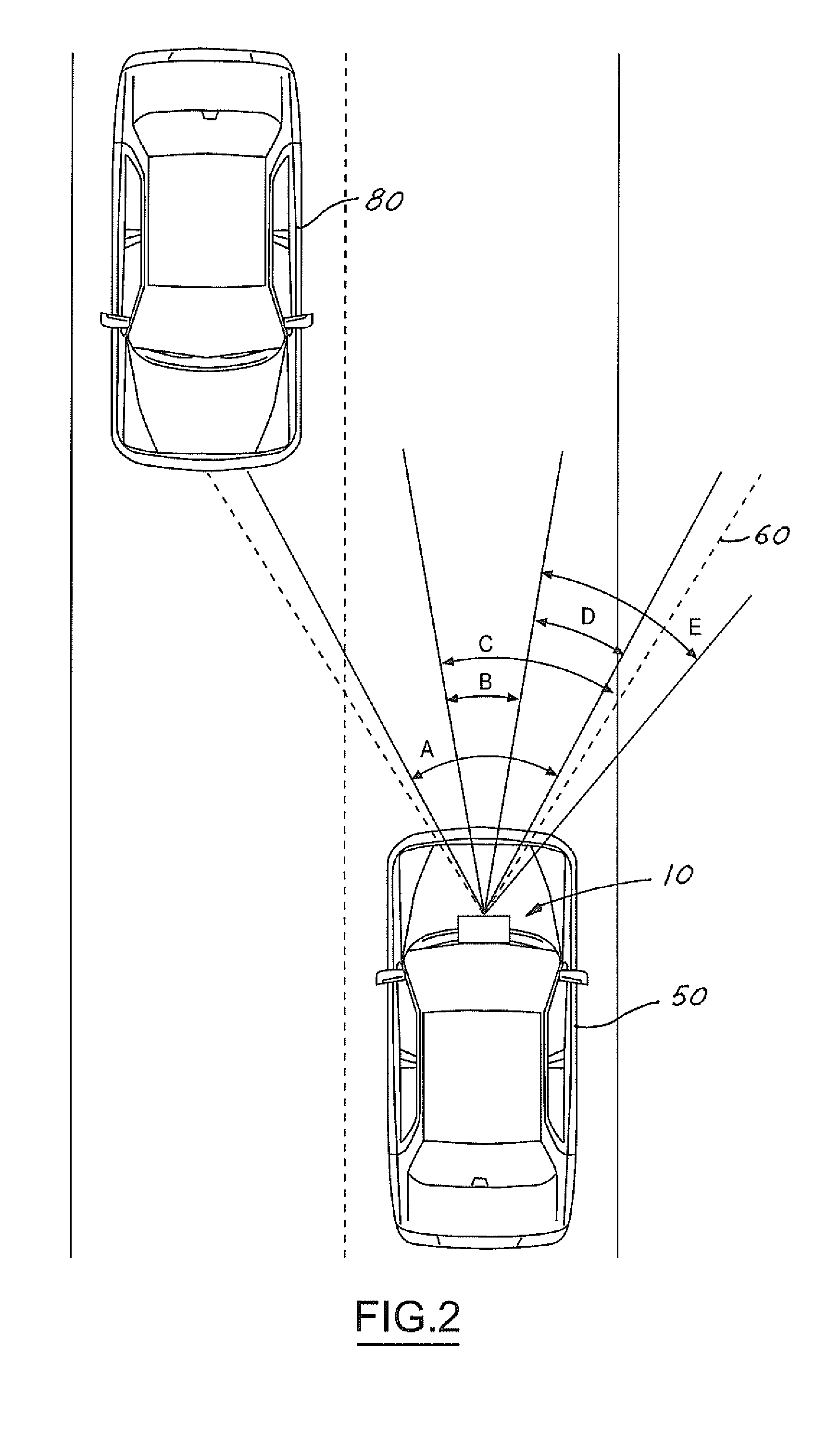
A vision system for a vehicle includes a light source generating an illumination beam, a receiver having a pixel array for capturing an image in response to at least a reflected portion of the illumination beam, the image corresponding to a first horizontal field of view (FOV) angle, and a controller coupled to the light source and the receiver. The controller receives a vehicle speed input and, in response, selects a portion of the image as a non-linear function of the vehicle speed to generate a second horizontal FOV angle for displaying to the vehicle operator. The displayed angular FOV decreases, non-linearly, as the vehicle speed increases.

Description

BACKGROUND OF INVENTION [0001] The present invention relates to night vision systems. More particularly, the present invention is related to an active night vision system with adaptive imaging. [0002] Night vision systems allow a vehicle occupant to better see objects during relatively low visible light level conditions, such as at nighttime. Night vision systems typically are classified as either passive night vision systems or active night vision systems. Passive systems simply detect ambient infrared light emitted from the objects within a particular environment. Active systems utilize a near infrared (NIR) light source to illuminate a target area and subsequently detect the NIR light reflected off objects within that area. [0003] Passive systems typically use far-infrared cameras that are characterized by low resolution and relatively low contrast. Such cameras must be located on the vehicle exterior in order to acquire requisite infrared energy in the operating environment. Ext...

Claims


Application Information

Patent Timeline
IPC IPC(8): G02B27/01B60R1/00B60R11/02
CPCB60R1/00B60R2300/103B60R2300/106B60R2300/8093B60R2300/30B60R2300/302B60R2300/8053B60R2300/205B60R1/24B60R1/28B60R1/30H04N7/18
Inventor WEBER, WILLES H.POTTER, TIMOTHYSHAFFER, ARIC
Owner FORD GLOBAL TECH LLC
Learn More