Electro-optical device, method for driving electro-optical device, driving circuit, and electronic apparatus

a technology of electrooptical devices and electronic devices, applied in optics, instruments, projectors, etc., can solve the problems of not providing all or parts of pixels in one or more data lines, and achieve the effect of reducing display quality

Inactive Publication Date: 2005-09-22
SEIKO EPSON CORP
View PDF2 Cites 26 Cited by
  • Summary
  • Abstract
  • Description
  • Claims
  • Application Information

AI Technical Summary

Benefits of technology

[0008] To achieve the object described above, an electro-optical device of the present invention includes pixels corresponding to intersections of a plurality of scanning lines and data lines; a scanning-line driving circuit for sequentially selecting the scanning lines; and a data-line driving circuit for sequentially selecting a plurality of blocks, each block including a predetermined number of the data lines, during a horizontal display period in which one of the scanning lines is selected, and simultaneously feeding image signals to the predetermined number of the data lines included in one of the blocks, during a period in which the block is selected. In the electro-optical device, the image signals are fed from the data lines to the pixels. A second block in the plurality of blocks is selected after a first block in the plurality of blocks is selected. A period in which the first block is selected partially overlaps with a period in which the second block is selected. Pixels corresponding to a plurality of data lines selected at the beginning of the horizontal display period do not contribute to display. In this electro-optical device, since one or more data lines are selected while another one or more data lines are selected, selection periods of data lines partially overlap with each other. Moreover, the number of image signal lines is equal to or larger than that of data lines simultaneously selected. This can prevent image degradation, such as ghost images, caused by the feeding of signals from the same image signal line to the data lines simultaneously selected. Capacitive coupling associated with such simultaneous selection affects both data lines in which their respective selection periods overlap with each other. However, since pixels corresponding to one or more data lines initially selected are affected differently from other pixels, they are not allowed to contribute to display, in the present invention, to prevent degradation in display quality.
[0010] It is preferable that the electro-optical device of the present invention further includes a plurality of image signal lines for feeding image signals. Moreover, it is preferable that the data-line driving circuit includes sampling switches, each switch being electrically connected to one of the data lines at one end and electrically connected to one of the image signal lines at the other end, which are configured such that those corresponding to selected data lines are turned on. This configuration allows for the proper feeding of image signals to data lines in which their respective selection periods partially overlap with each other.
[0011] In the configuration for feeding image signals via the image signal lines, it is preferable that the image signals are divided into the image signal lines such that signals for defining the gradation of pixels are expanded along the time axis according to the number of the image signal lines, in synchronization with the selection of data lines in the data-line driving circuit, and fed to the selected data lines. This configuration can increase the time for which image signals are fed to the data lines.
[0012] Moreover, if the data-line driving circuit includes the sampling switches, the data-line driving circuit may further include logic circuits, each logic circuit being provided for shaping one pulse such that the one pulse overlaps with a pulse adjacent to the one pulse, and outputting the shaped pulse as a sampling signal for turning on or off one of the sampling switches. Moreover, the logic circuits may be configured such that each logic circuit performs a logic operation between the one pulse and any of a plurality of enable signals that are sequentially phase-shifted. This configuration allows for the overlapping selection of the data lines.
[0014] The present invention can be conceptualized not only as an electro-optical device, but also as a driving method and a driving circuit. Moreover, degradation in display quality can become less noticeable in the electronic apparatus of the present invention, as the electronic apparatus includes the above-described electro-optical device as a display unit.

Problems solved by technology

Furthermore, all or parts of the pixels may not be provided in one or more data lines selected at the beginning of a period during which one of the scanning lines is selected.

Method used


Image

  • Electro-optical device, method for driving electro-optical device, driving circuit, and electronic apparatus
  • Electro-optical device, method for driving electro-optical device, driving circuit, and electronic apparatus
  • Electro-optical device, method for driving electro-optical device, driving circuit, and electronic apparatus

Examples


first embodiment

1. First Embodiment

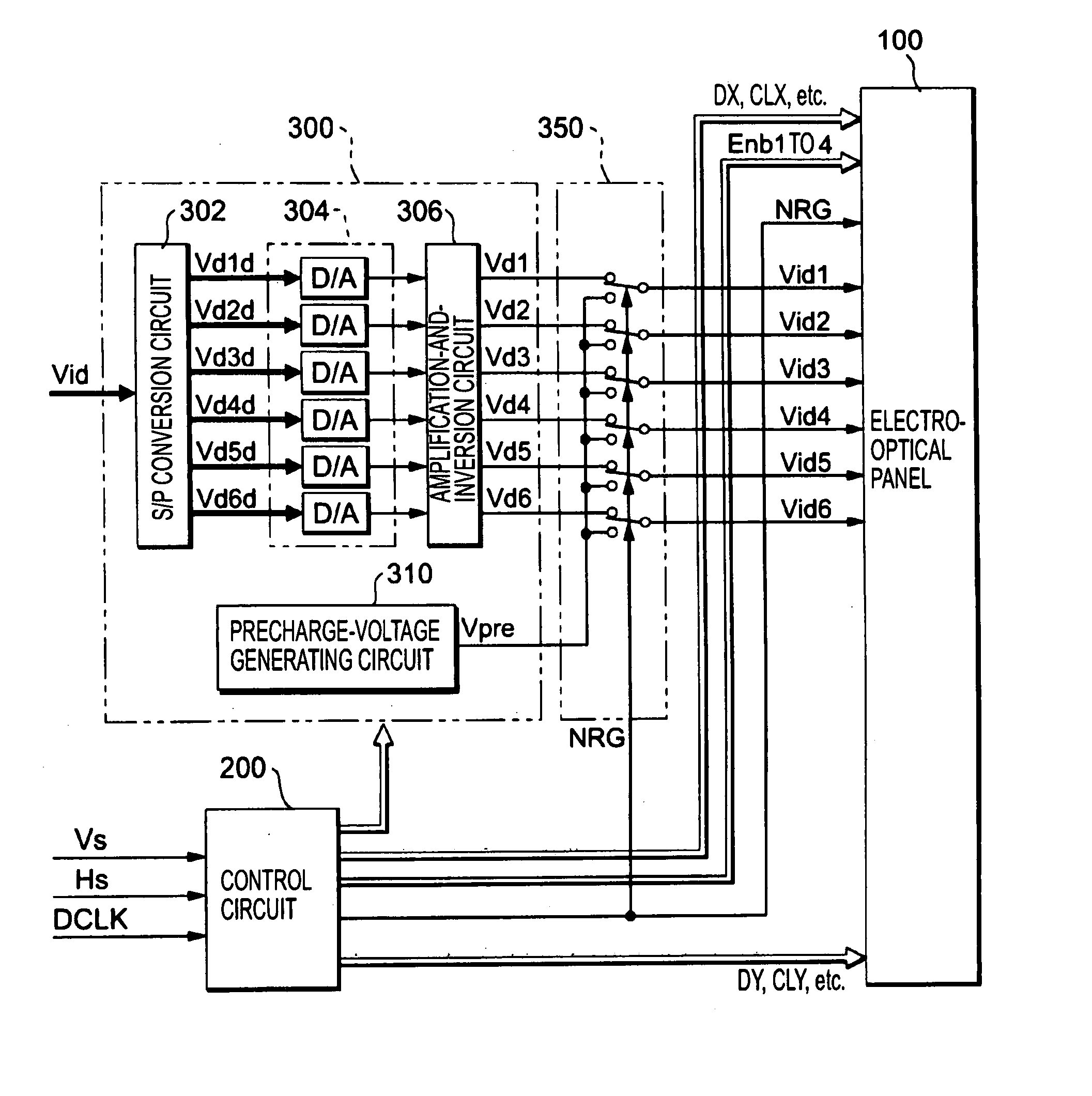
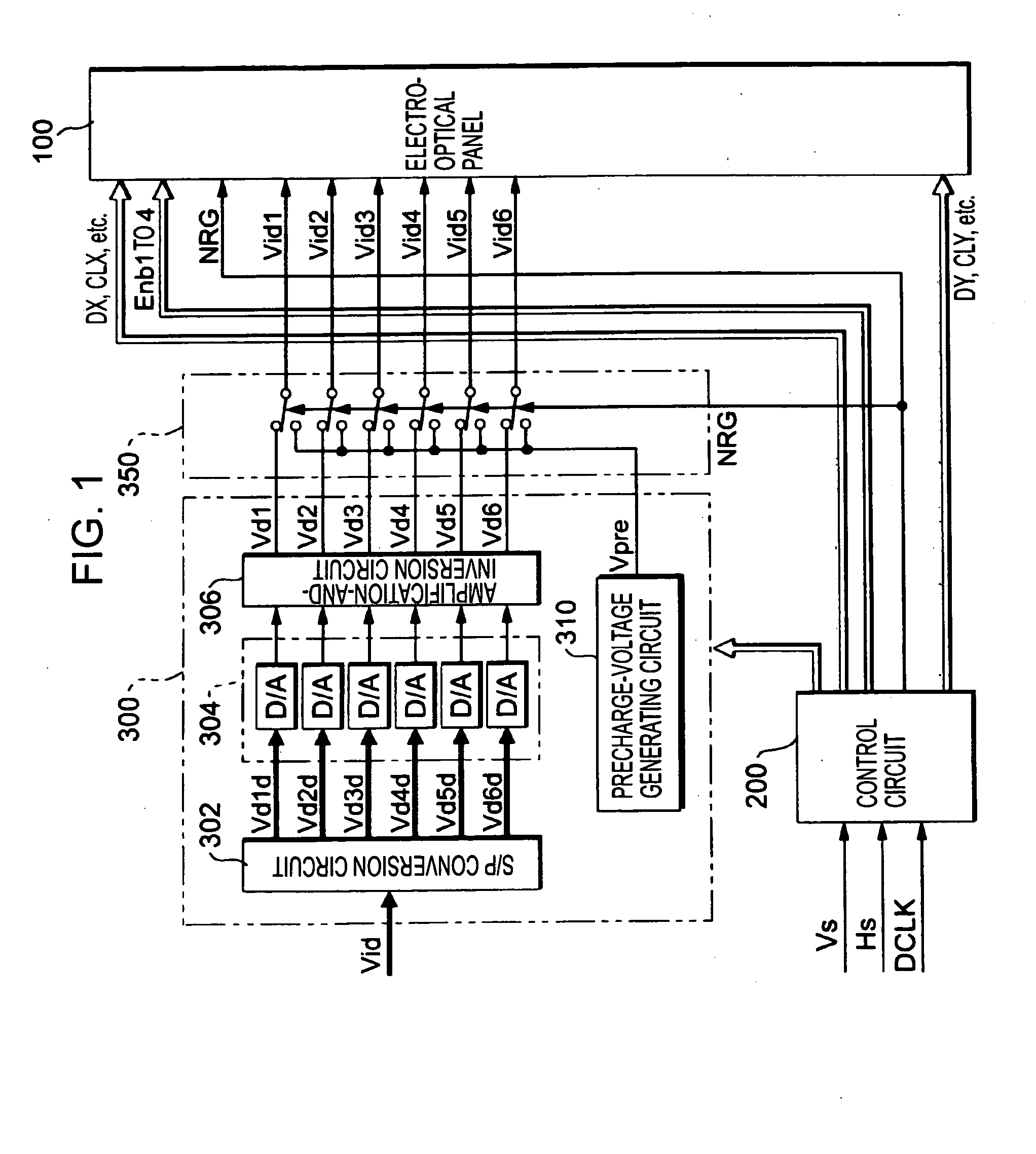
[0027]FIG. 1 is a block diagram showing the overall structure of an electro-optical device according to an embodiment of the present invention. As shown in the drawing, the electro-optical device includes an electro-optical panel 100, a control circuit 200, and a processing circuit 300. The control circuit 200 generates timing signals, clock signals, and the like, for controlling each section of the electro-optical device, according to a vertical scanning signal Vs, a horizontal scanning signal Hs, and a dot clock signal DCLK that are supplied from a higher-level apparatus (not shown).

[0028] The processing circuit 300 includes an S / P conversion circuit 302, a D / A converter group 304, and an amplification-and-inversion circuit 306.

[0029] Video data Vid, which designates the gradation (brightness) of each pixel by a digital value, is serially supplied from the higher-level apparatus, in synchronization with the vertical scanning signal Vs, the horizontal scanning ...


PUM

PropertyMeasurementUnit
angleaaaaaaaaaa
brightnessaaaaaaaaaa
phase-shiftedaaaaaaaaaa

Abstract

According to exemplary embodiments, three data lines are selected in a horizontal scanning period during which a scanning line is selected. Image signals according to the gradation of pixels corresponding to the intersections of the selected scanning line and the selected data lines are sampled for the selected data lines. While the three data lines are selected, the subsequent three data lines are also selected. Then, image signals according to the gradation of pixels corresponding to the intersections of the selected scanning line and the subsequent three data lines are sampled for the subsequent three data lines. The pixels corresponding to the three data lines selected at the beginning of the horizontal scanning period are included in a non-display area so that they do not contribute to display.

Description

TECHNICAL FIELD [0001] The present invention relates to a technique for preventing the degradation of display quality when one or more data lines are driven together. BACKGROUND ART [0002] A projector for forming small images using an electro-optical panel, such as a liquid-crystal panel, and enlarging and projecting such small images onto a screen, wall, or the like, using an optical system is becoming widespread these days. The projector itself is not capable of creating images, but receives video data (or video signals) from a higher-level apparatus, such as a personal computer or a television tuner. The video data for defining the gradation (brightness) of pixels is fed in the manner of vertical and horizontal scanning of a matrix of pixels. It is thus appropriate that the electro-optical panel used in the projector be driven in such a manner. Therefore, the electro-optical panel used in the projector is generally driven by a dot-sequential method in which, while scanning lines ...

Claims


Application Information

Patent Timeline
Patent Type & Authority Applications(United States)
IPC IPC(8): G02F1/133G09G3/36
CPCG09G2310/0218G09G3/3688G02F1/133G03B21/00G09G3/36
Inventor ISHII, KENYA
Owner SEIKO EPSON CORP
Why Eureka
Try Eureka