Recording head and recorder comprising such recording head

a recording head and recording head technology, applied in the field of recording heads, can solve the problems of limited current value which can be supplied at once, limited electrical power supply capacity of the electric power supply of the printer apparatus, and increase of wiring resistance and resistance variations, and achieve the effect of stably recording

Inactive Publication Date: 2005-09-22
CANON KK
View PDF16 Cites 16 Cited by
  • Summary
  • Abstract
  • Description
  • Claims
  • Application Information

AI Technical Summary

Benefits of technology

[0016] The present invention has been made in consideration of the prior art, and has as its feature to provide a recording head which can stably record at a high speed even if the number of concurrently driven recording elements increases, and a recording apparatus having the recording head.
[0017] It is another feature of the present invention to provide a recording head which drives recording elements by a constant current and can adjust the constant current value to apply uniform energy to the recording elements, and a recording apparatus having the recording head.

Problems solved by technology

However, the electric power supply capacity of the electric power supply of a printer apparatus is limited, and a current value which can be supplied at once is limited by, e.g., a voltage drop caused by the resistance of a wiring line extending from the power supply to the heater.
This problem occurs also when the heater substrate is downsized, and the wiring resistance and variations in resistance increase.
When energy applied to a heater is too small, ink discharge becomes unstable; when the energy is too large, the heater durability degrades.
However, large fluctuations in voltage applied to a heater degrade the heater durability and make ink discharge unstable, as described above.
However, as the number of concurrently driven heaters increases, the voltage drop becomes larger on the common wiring line.
The voltage application time in heater driving becomes longer, making it difficult to drive a heater at a high speed.
In this case, constant current sources equal in number to printing elements are necessary, the area of the heater substrate becomes much larger than that in a conventional driving method, and the cost of the heater substrate becomes higher.
It is difficult to reduce variations in output current between a plurality of constant current sources particularly on a heater substrate having a larger number of heaters for higher speed and higher precision of printing by the printer.

Method used


Image

  • Recording head and recorder comprising such recording head
  • Recording head and recorder comprising such recording head
  • Recording head and recorder comprising such recording head

Examples


first embodiment

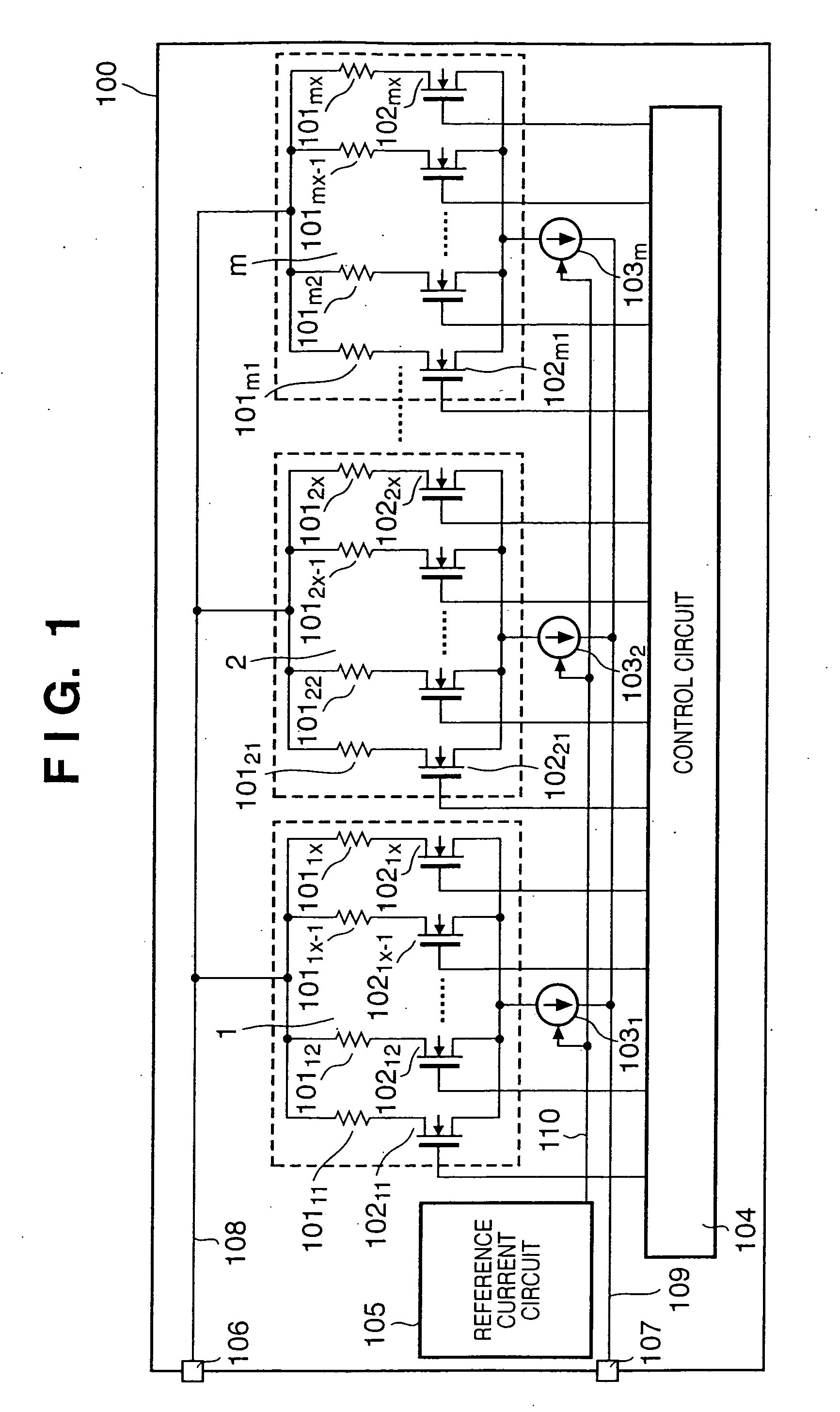
[0041]FIG. 1 is a circuit diagram for explaining the arrangement of a heater driving circuit mounted on the heater substrate of an inkjet printhead according to the first embodiment of the present invention.

[0042] In FIG. 1, reference numerals 10111 to 101mx denote heaters (heater resistors) for printing. A current flows to each heater to generate heat, and a corresponding nozzle discharges an ink droplet. The heaters 10111 to 101mx are divided into blocks (groups) 1 to m, and each block includes x heaters, and x NMOS transistors which are arranged in correspondence with the respective heaters. Reference numerals 10211 to 102mx denote NMOS transistors for ON / OFF-controlling energization to corresponding heaters. Reference numerals 1031 to 103m denote constant current sources which are arranged for the respective blocks. Reference numeral 104 denotes a control circuit which controls ON / OFF operation of each NMOS transistor 102 in accordance with printing data to be printed. Referenc...

second embodiment

[0056]FIG. 4 is a circuit diagram for explaining the arrangement of a head driving circuit in a printhead according to the second embodiment of the present invention. In the second embodiment, the constant current sources 1031 to 103m in the first embodiment are implemented by NMOS transistors 4011 to 401m.

[0057] The drains of the NMOS transistors 4011 to 401m are respectively connected to the sources of NMOS transistors 10211 to 102nx. The gates of the NMOS transistors 4011 to 401m receive a control signal 110 from a reference current circuit 105, and the drains of the NMOS transistors 4011 to 401m output currents. The output currents are controlled by the gate voltages of the MOS transistors 4011 to 401m that are connected to the reference current circuit 105.

[0058] The operation of the NMOS transistors 4011 to 401m in FIG. 4 will be explained with reference to FIGS. 5 and 6.

[0059]FIG. 5 is a graph showing the general static characteristic of an NMOS transistor used as each of ...

third embodiment

[0062]FIG. 7 is a circuit diagram for explaining a head driving circuit in a printhead according to the third embodiment of the present invention. In the third embodiment, the sources of NMOS transistors 7011 to 701m are connected to the drains of the NMOS transistors 4011 to 401m in FIG. 4, and two corresponding NMOS transistors are cascade-connected in series to form a constant current source. The gates of the NMOS transistors 7011 to 701m are also connected to a reference current circuit 105a. The third embodiment will explain a structure of two transistors, but the present invention can also be applied to a structure of a larger number of transistors.

[0063] The NMOS transistors 7011 to 701m operate as grounded-gate transistors, and fix the drain voltages of the NMOS transistors 4011 to 401m on the basis of the potentials between the gates and sources of the NMOS transistors 7011 to 701m. The gate voltages of the NMOS transistors 7011 to 701m are so set as to operate the NMOS tr...


PUM


Abstract

A recording head having a plurality of recording elements comprises a plurality of switching elements, each provided in correspondence to each of the plurality of recording elements, constant current sources, each provided in correspondence to each of groups in which the plurality of recording elements are divided, for flowing a constant current into a plurality of recording elements of each group, and a constant current control circuit for controlling the constant current supplied from the constant current sources, and the recording elements are driven by the constant current.

Description

TECHNICAL FIELD [0001] The present invention relates to a recording head having a plurality of recording elements and a recording apparatus having the recording head. BACKGROUND ART [0002] There has conventionally been known an inkjet head which causes a heater arranged in the nozzle of a printhead to generate thermal energy, bubbles ink near the heater by using thermal energy, and discharges ink from the nozzle to print. FIG. 11 shows an example of a heater driving circuit in the inkjet head. [0003] To print at a high speed, heaters are desirably concurrently driven as many as possible to simultaneously discharge ink from many nozzles. However, the electric power supply capacity of the electric power supply of a printer apparatus is limited, and a current value which can be supplied at once is limited by, e.g., a voltage drop caused by the resistance of a wiring line extending from the power supply to the heater. For this reason, time divisional driving of driving a plurality of he...

Claims


Application Information

Patent Timeline
Patent Type & Authority Applications(United States)
IPC IPC(8): B41J2/05
CPCB41J2/04541B41J2/04543B41J2/0458B41J2/04555B41J2/0457B41J2/0455B41J2/04501
Inventor HIRAYAMA, NOBUYUKI
Owner CANON KK
Why Eureka
Try Eureka