
Liquid crystal display device

a display device and liquid crystal technology, applied in the field of liquid crystal display devices, can solve the problems of high production cost, complicated processing step of louver sheet, and low light transmittance of the method used to achieve the effect of low light transmittan

Inactive Publication Date: 2005-09-22
TOSHIBA MATSUSHITA DISPLAY TECH
View PDF4 Cites 41 Cited by
  • Summary
  • Abstract
  • Description
  • Claims
  • Application Information

AI Technical Summary

Benefits of technology

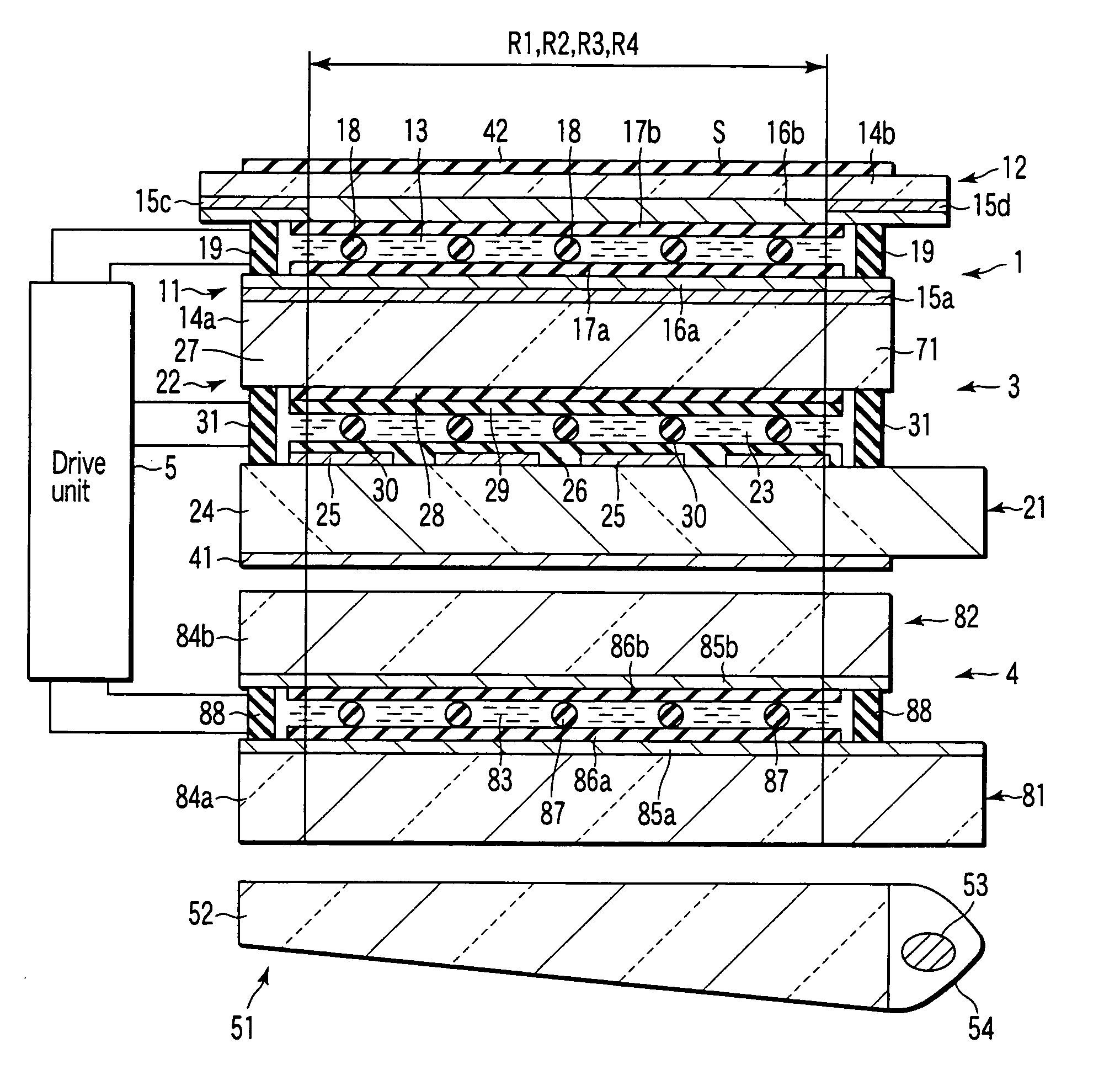
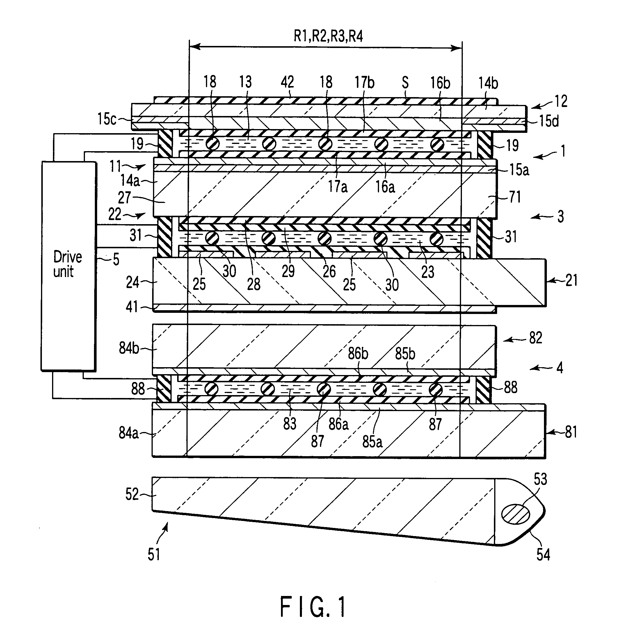
[0017] a drive unit which drives the phase control liquid crystal element and the luminance visual angle control liquid crystal element in accordance with a respective one of the plurality of display modes.

Problems solved by technology

Therefore, the method using a louver sheet entails a drawback of a low light transmittance.
The processing step for the louver sheet is complicated and the production cost is high.
Further, when attaching or detaching a louver sheet, it takes the user time and labor.
In the meantime, the method that uses a pair of polarizing glasses, entails the drawback where the displayed image cannot be monitored publicly by some other persons.

Method used


Image

  • Liquid crystal display device
  • Liquid crystal display device
  • Liquid crystal display device

Examples


Embodiment Construction

[0035] A liquid crystal display device, according to an embodiment of the present invention, will now be described in detail with reference to accompanying drawings.

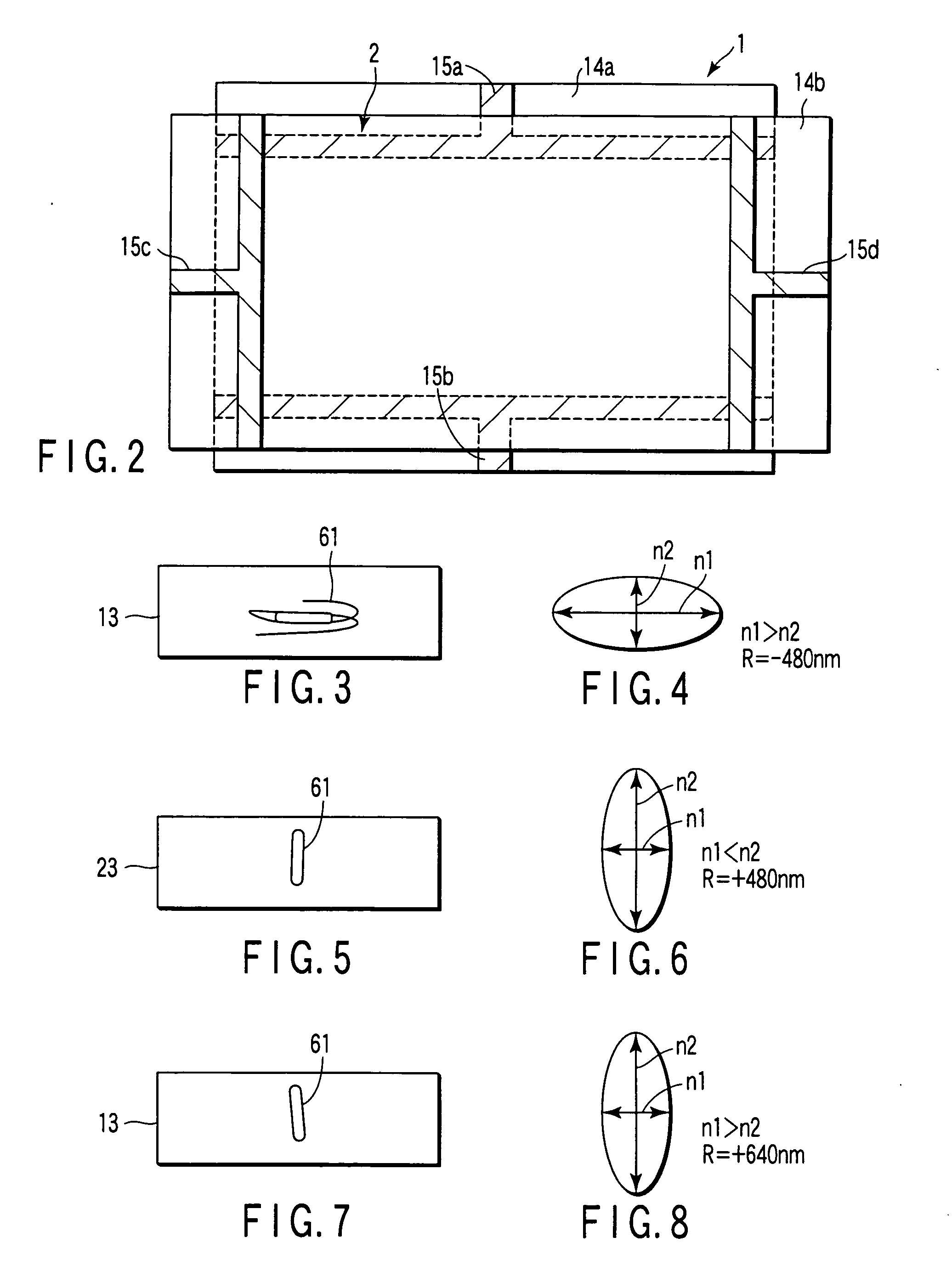
[0036] As shown in FIG. 1, the liquid crystal display device includes a phase control liquid crystal element 1, a liquid crystal display panel 3, a first polarizing plate 41, a second polarizing plate 42, a backlight unit 51, a luminance visual angle control liquid crystal element 4 and a drive unit 5. The phase control liquid crystal element 1 includes a first substrate 11, a second substrate 12 which is arranged opposite to the first substrate with a predetermined gap therebetween, and a first liquid crystal layer 13. The first substrate 11 includes a first sheet 14a made of, for example, polyester film or glass, as a transparent insulating substrate, a first electrode 16a arranged on the first sheet and made of a transparent conductive material such as ITO (indium tin oxide), and a first alignment film 17a arranged o...


PUM

PropertyMeasurementUnit
twisting angleaaaaaaaaaa
pretilt angleaaaaaaaaaa
refractive indexaaaaaaaaaa

Abstract

A liquid crystal display device having a plurality of display modes of viewing angle properties different from each other, comprising a liquid crystal display panel, a backlight unit, a phase control liquid crystal element, a luminance visual angle control liquid crystal element, and a drive unit. The drive unit drives the phase control liquid crystal element and the luminance visual angle control liquid crystal element in accordance with a respective one of the plurality of display modes.

Description

CROSS-REFERENCE TO RELATED APPLICATIONS [0001] This application is based upon and claims the benefit of priority from prior Japanese Patent Application No. 2004-077642, filed Mar. 18, 2004, the entire contents of which are incorporated herein by reference. BACKGROUND OF THE INVENTION[0002] 1. Field of the Invention [0003] The present invention relates to a liquid crystal display device. [0004] 2. Description of the Related Art [0005] Recently, liquid crystal display device are applied in various fields including note-type personal computers, monitors, car navigations, functional calculators, small- to middle-sized televisions, large-sized televisions, mobile telephones and electronic notepads. [0006] These liquid crystal displays have wide viewing angles and high contrasts due to the realization of the thin film transistor (TFTs), and the application of the in-plane switching mode (IPS), multi-vertical align mode (MVA) and wide view film. [0007] Of these liquid crystal display devic...

Claims


Application Information

Patent Timeline
Patent Type & Authority Applications(United States)
IPC IPC(8): G02F1/13G02F1/133G02F1/1333G02F1/1335G02F1/1347G06F3/041
CPCG02F1/1323G02F1/13476G02F1/13471G02F1/133504G02F1/1335
Inventor HISTAKE, YUZO
Owner TOSHIBA MATSUSHITA DISPLAY TECH
Learn More