Optical fiber inspection device

Active Publication Date: 2005-09-22
PROMET INT
View PDF19 Cites 21 Cited by
  • Summary
  • Abstract
  • Description
  • Claims
  • Application Information

AI Technical Summary

Benefits of technology

[0006] The present invention provides an inspection system for inspecting a surface of an optical specimen. The inspection system includes an optical testing device having a main body and an optical axis. The optical testing device includes an optical imaging system housed in the main body. The optical imaging system includes imaging components for acquiring

Problems solved by technology

Optical microscopes magnify undesirable surface defects.
These optical instruments, however, tend to be large, expensive and require a great amount of time to inspect an endface surface.
These limitations make it difficult for users of polishing mechanisms to efficiently test and retest fiber or fiber connector endfaces.
Manipulation and alignment of a fiber optic or fiber connector end

Method used


Image

  • Optical fiber inspection device
  • Optical fiber inspection device
  • Optical fiber inspection device

Examples


Embodiment Construction

[0021] Although embodiments of the present invention will be described in the context of testing an endface surface of optical fibers or fiber connectors, the present invention is applicable to other types of microscopic optical surfaces, such as lens arrays and other suitable surfaces.

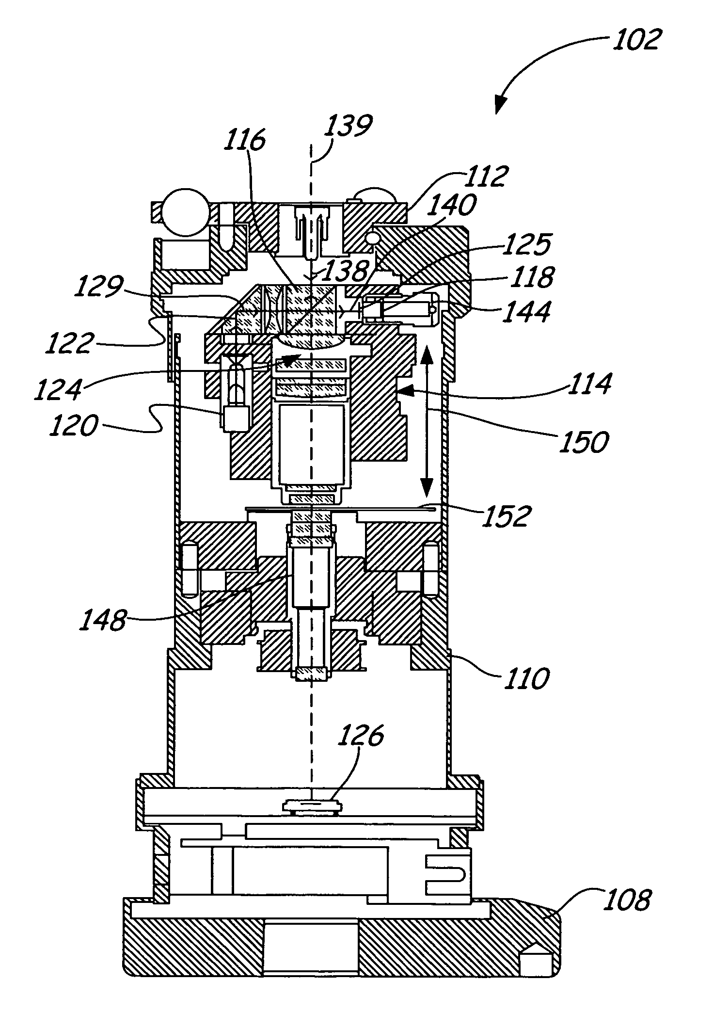
[0022]FIG. 1 is a perspective view of an inspection system 100 in accordance with an embodiment of the present invention. Inspection system 100 includes an optical testing device 102 coupled to a computing device 104 preferably by a cable 106. Optical testing device 102 is configured to receive and fixedly secure an optical specimen 105, such as an optical fiber or fiber connector endface, for inspection. Computing device 104 includes software configured to display measurement and inspection results and to initiate various electrical functions of optical testing device 102. Optical testing device 102 includes an interface 107 adapted to communicate with computing device 104. In one embodiment, interf...


PUM


Abstract

The present invention provides an inspection system for inspecting a surface of an optical specimen. The inspection system includes an optical testing device having a main body and an optical axis. The optical testing device includes an optical imaging system housed in the main body. The optical imaging system includes imaging components for acquiring a microscope visual image and for acquiring at least one interference fringe image of the surface of the optical specimen. The optical testing device also includes a translational mechanism housed in the main body and configured to allow linear movement of the optical imaging system and to prevent off-axis movement of the optical imaging system.

Description

[0001] The present application is based on and claims the benefit of U.S. provisional patent application Ser. No. 60 / 540,476, filed Jan. 30, 2004, the content of which is hereby incorporated by reference in its entirety.FIELD OF THE INVENTION [0002] The present invention relates to an optical testing device. More particularly, the present invention relates to an optical testing device used for inspection of optical specimens. BACKGROUND OF THE INVENTION [0003] To join two fibers or fiber optic connectors together, the quality of a fiber endface or fiber connector endface needs to meet certain standards to maximize coupling efficiency and ensure proper operation of the fiber or fiber connector. Generally, a fiber endface or fiber connector endface has a desirable geometry or topography as well as an acceptable surface quality. A desirable surface geometry and acceptable surface quality is usually achieved through an optical polishing process and tested by one or more special optical ...

Claims


Application Information

Patent Timeline
IPC IPC(8): G01B11/24G01B11/30G01N21/88G01N21/952
CPCG01B11/2441G01N21/952G01N21/8806G01B11/303
Inventor KOUDELKA, LUBOMIRARNOLD, STEVEN M.KOUDELKA, PETER DAVIDECKMAN, RYAN ELLIOTLINDMARK, ERIC KARL
Owner PROMET INT
Why Eureka
Try Eureka