

Zoom lens and electronic imaging apparatus having the same
a technology of electronic imaging apparatus and zoom lens, which is applied in the field of zoom lens, can solve the problems of small known zoom lens downsized so as to be mounted in the mobile phone, and the digital camera has become increasingly compact and slim, and achieves the effect of cost reduction
- Summary
- Abstract
- Description
- Claims
- Application Information
AI Technical Summary
Benefits of technology
Problems solved by technology
Method used
Image

Examples
first embodiment
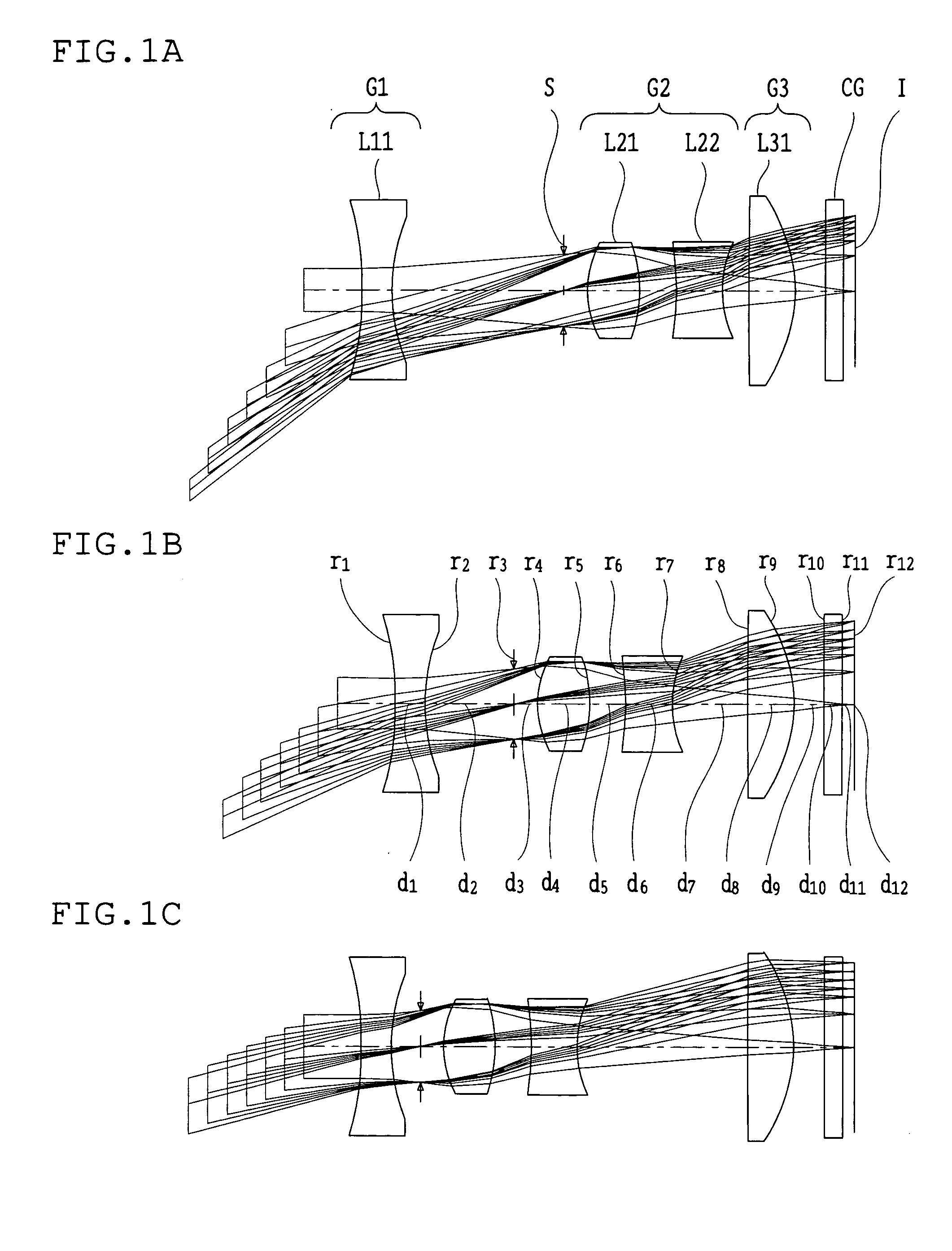
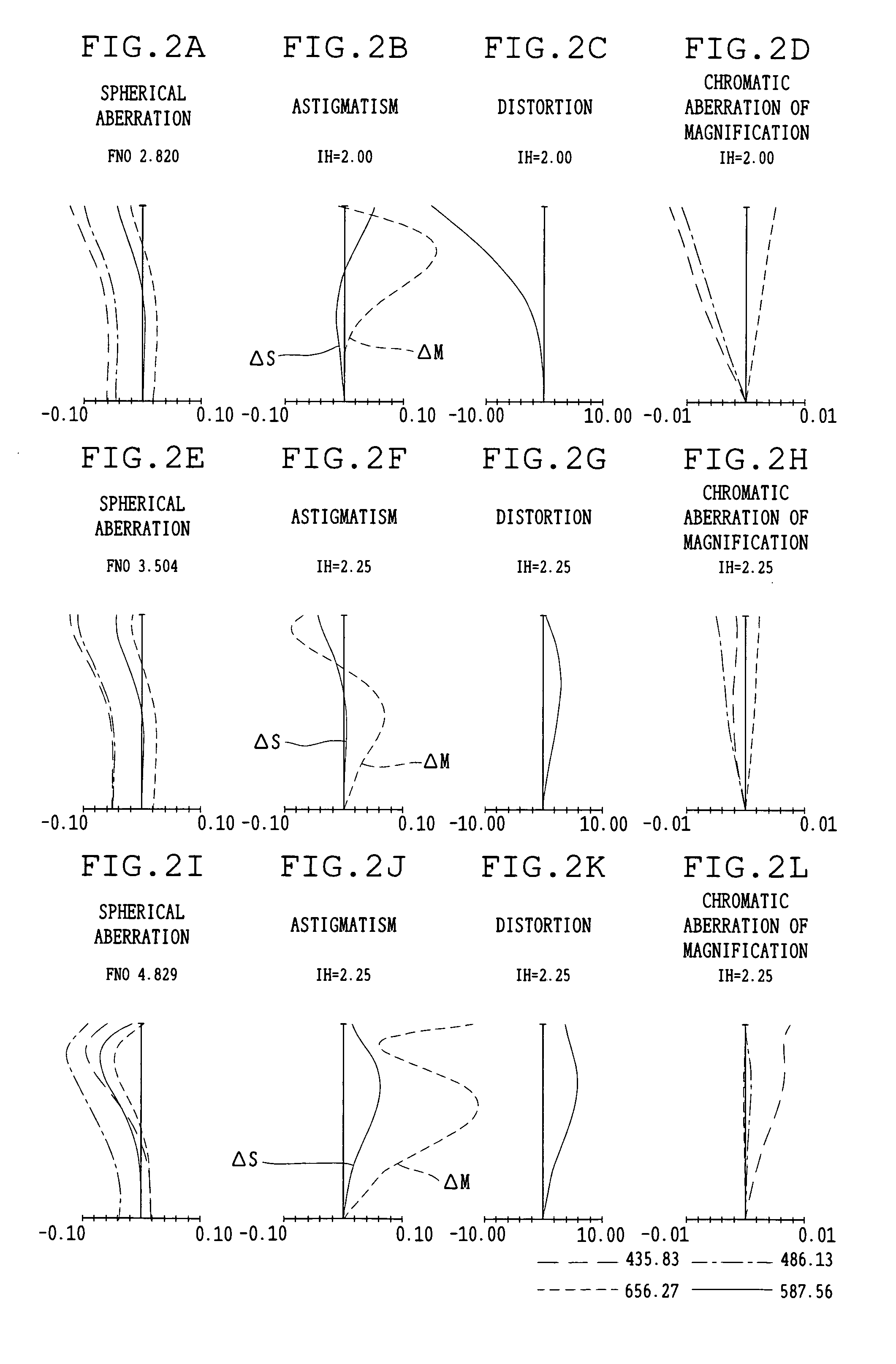
[0114]FIGS. 1A-1C show optical arrangements in the first embodiment of the zoom lens of the present invention. FIGS. 2A-2L show aberration characteristics of the zoom lens in the first embodiment. FIGS. 3A-3L show coma characteristics of the zoom lens in the first embodiment.
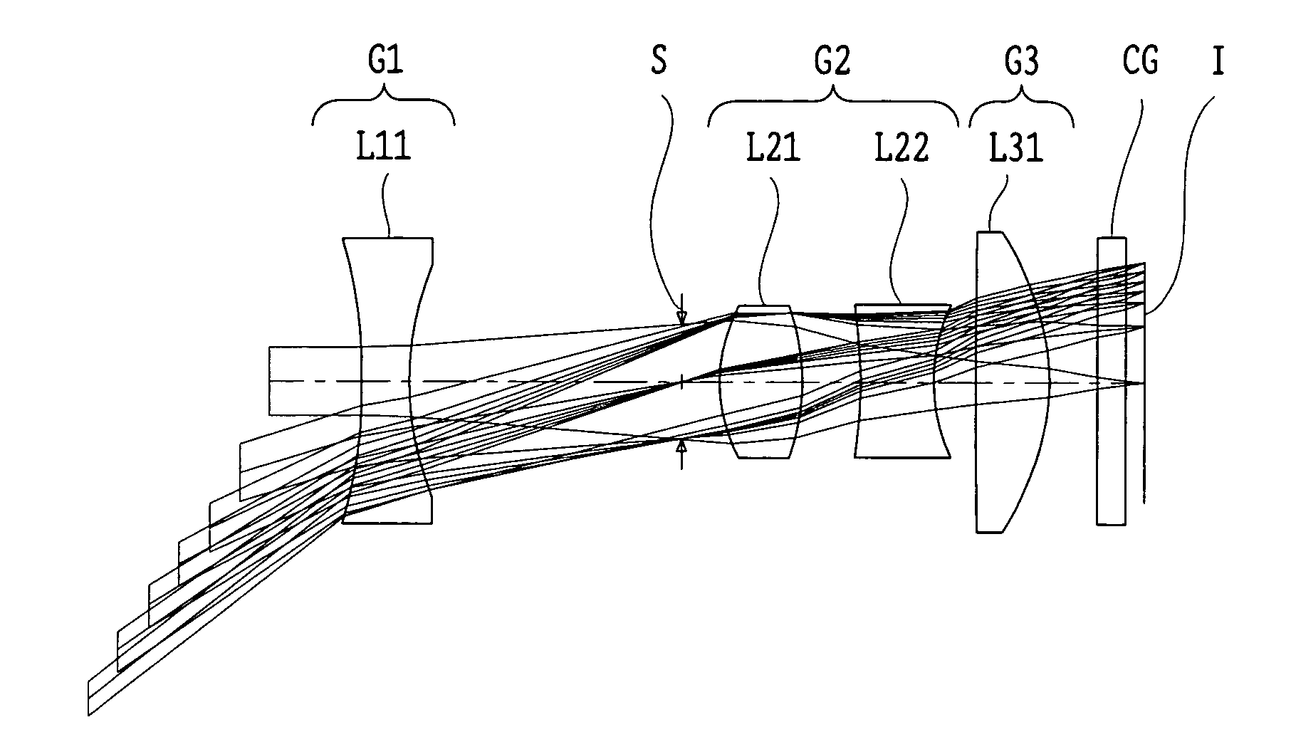
[0115] As shown in FIG. 1A, the zoom lens of the first embodiment comprises, in order from the object side, a first lens unit G1, an aperture stop S, a second lens unit G2, and a third lens unit G3. Also, in this figure, reference symbol CG represents a cover glass and I represents the imaging surface of the image sensor.
[0116] The first lens unit G1 is constructed with a biconcave lens L11. The second lens unit G2 includes a biconvex lens L21 and a biconcave lens L22, having positive refracting power as a whole. The third lens unit G3 is constructed with a biconvex lens L31.
[0117] When the magnification of the zoom lens is changed in the range from the wide-angle position to the telephoto position, the first...
second embodiment
[0127]FIGS. 4A-4C show optical arrangements in the second embodiment of the zoom lens of the present invention. FIGS. 5A-5L show aberration characteristics of the zoom lens in the second embodiment. FIGS. 6A-6L show coma characteristics of the zoom lens in the second embodiment.
[0128] As shown in FIG. 4A, the zoom lens of the second embodiment comprises, in order from the object side, the first lens unit G1, the aperture stop S, the second lens unit G2, and the third lens unit G3. In this figure, again reference symbol CG represents a cover glass and I represents the imaging surface of the image sensor.
[0129] The first lens unit G1 is constructed with the biconcave lens L11. The second lens unit G2 includes the biconvex lens L21 and the biconcave lens L22, having positive refracting power as a whole. The third lens unit G3 is constructed with a cemented doublet of a negative meniscus lens L31′ with a convex surface facing the object side and a biconvex lens L32, having positive re...
third embodiment
[0137]FIGS. 7A-7C show optical arrangements in the third embodiment of the zoom lens of the present invention. FIGS. 8A-8L show aberration characteristics of the zoom lens in the third embodiment. FIGS. 9A-9L show coma characteristics of the zoom lens in the third embodiment.
[0138] As shown in FIG. 7A, the zoom lens of the third embodiment comprises, in order from the object side, the first lens unit G1, the aperture stop S, the second lens unit G2, and the third lens unit G3. In this figure, again reference symbol CG represents a cover glass and I represents the imaging surface of the image sensor.
[0139] The first lens unit G1 is constructed with a cemented doublet of an aspherical lens L11′ whose object-side surface is concave toward the object side and whose image-side surface is concave toward the image side at the lens middle and convex toward the image side on the lens periphery and an aspherical lens L12 whose object-side surface is convex toward the object side of the lens...
PUM
 Abstract
Description
Claims
Application Information