

Methods and systems for multi-modality imaging
- Summary
- Abstract
- Description
- Claims
- Application Information
AI Technical Summary
Benefits of technology
Problems solved by technology
Method used
Image

Examples
Embodiment Construction
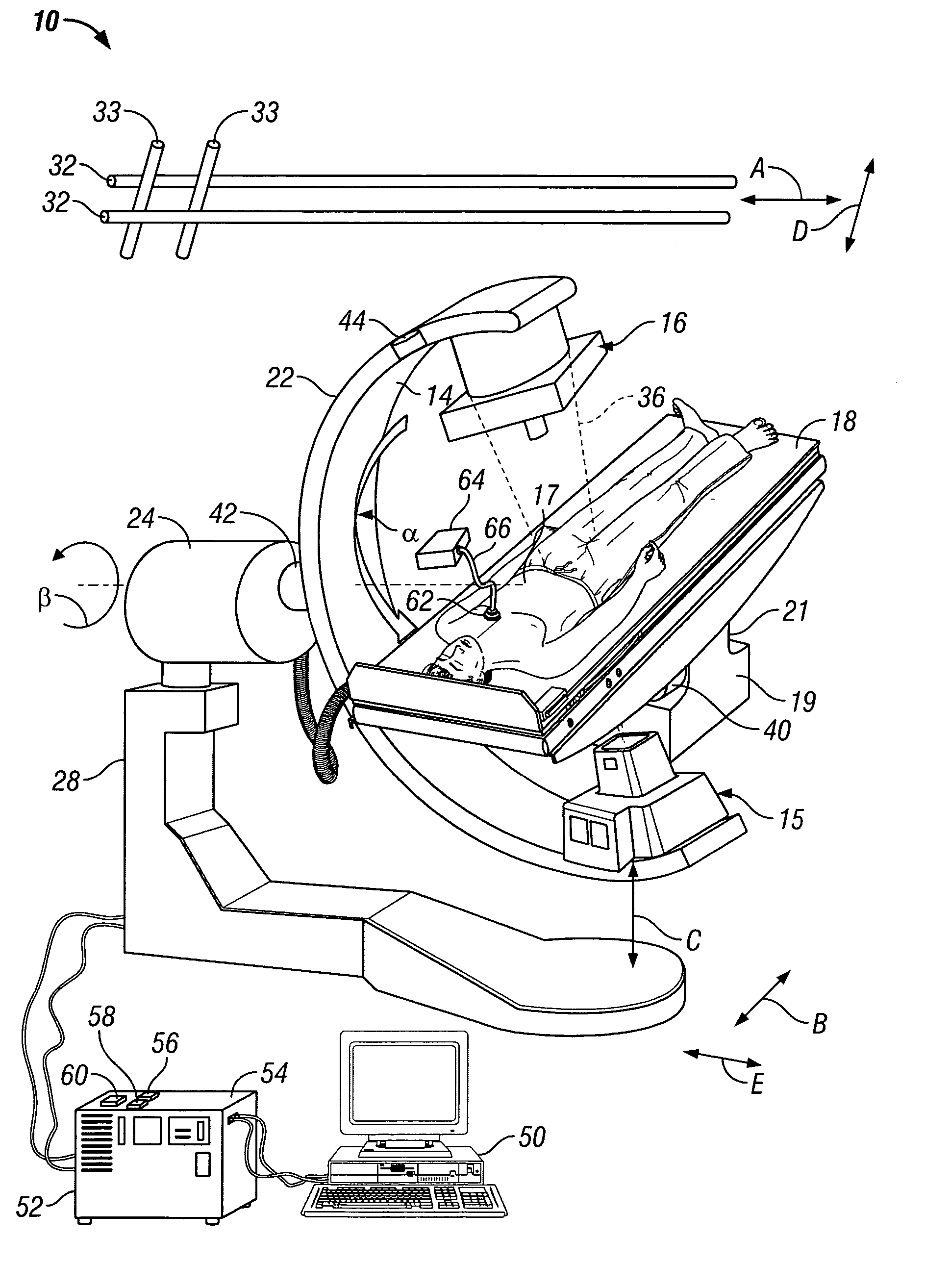
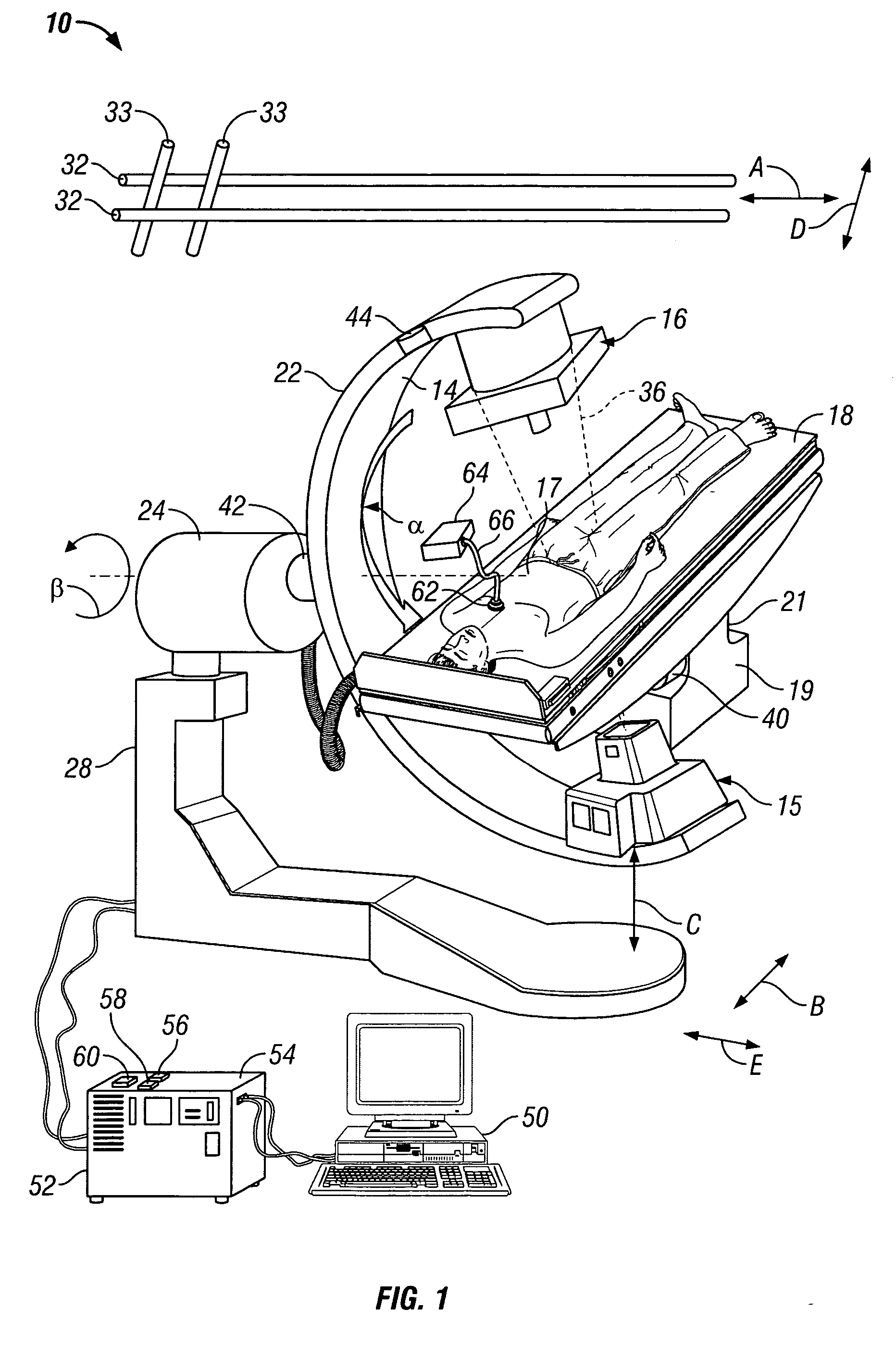
[0009] Although the present invention is described in the context of a an exemplary C-arm gantry, it should be understood that any configuration of gantry capable of performing the functions described herein is contemplated as being used.
[0010]FIG. 1 is a schematic illustration of an imaging system 10 in accordance with an exemplary embodiment of the present invention. An X-ray source 15 and a dual x-ray / gamma ray detector 16 are attached to the two ends of a C-arm 14. X-ray source 15 generates X-rays when applied with a high voltage (e.g., 10,000 volts) from a high voltage generator (not shown). In the exemplary embodiment, x-ray source 15 generates a cone-beam of x-ray photons that are projected from x-ray source 15 towards dual x-ray / gamma ray detector 16 in a diverging conical projection at a predetermined fan angle. In an alternative embodiment, x-ray source 15 generates a fan beam of x-ray photons. Dual x-ray / gamma ray detector 16 may be fabricated of a flat panel Cadmium Zin...
PUM
| Property | Measurement | Unit |
|---|---|---|
| fan angle | aaaaa | aaaaa |
| fan angle | aaaaa | aaaaa |
| angle | aaaaa | aaaaa |
Abstract
Description
Claims
Application Information