Active noise tuning system

a technology of active noise and tuning system, applied in the field of signal processing, can solve the problems of unstable stability, unsuitable general application wideband systems, and active noise control systems that attenuate undeired noise, and achieve the effect of improving noise suppression

Active Publication Date: 2005-09-22
HARMAN BECKER AUTOMOTIVE SYST
View PDF4 Cites 233 Cited by
  • Summary
  • Abstract
  • Description
  • Claims
  • Application Information

AI Technical Summary

Benefits of technology

[0013] There is a need for active noise tuning systems with improved noise suppression.
[0014] An active noise tuning system for tuning an acoustic noise generated by a noise source at a listening location comprises a sound sensor (e.g., microphone) that is arranged in the surroundings of the listening location and a noise signal source for generating an electrical signal that corresponds to the acoustic noise of the noise source. An adaptive filter that is controlled by control signals is connected downstream of the noise signal source. A sound reproduction device (e.g., loudspeaker) is connected to the adaptive filter in order to irradiate the noise signal filtered by the adaptive filter is arranged in the surroundings of the listening location, a secondary path transfer function occurring between the sound reproduction device and sound sensor. A first filter having a transfer function that models the secondary path transfer function is connected to the noise signal source. The first filter and the sound sensor provide the control signal

Problems solved by technology

While systems are known for compensating periodic noise signals that are related to the rotational speed there are already applicable implementations available, while broadband systems are not suitable for general applications owing to the very high computing capacity required.
Active noise control systems attenuate undesired noise.
In most cases, stability problems occur with the feedback structure, in particular with a pure feedback structure, as it is very difficult to avoid unwanted direct feedback.
It is difficult in active noise control systems that employ to find a suitable location for the reference microphone 5 an

Method used


Image

  • Active noise tuning system
  • Active noise tuning system
  • Active noise tuning system

Examples


Embodiment Construction

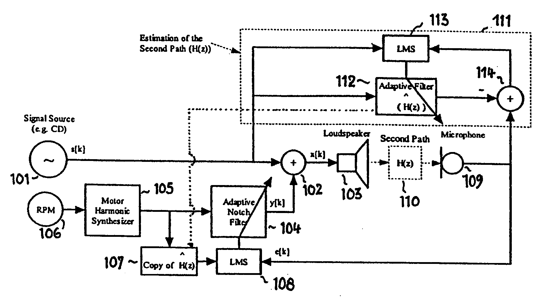
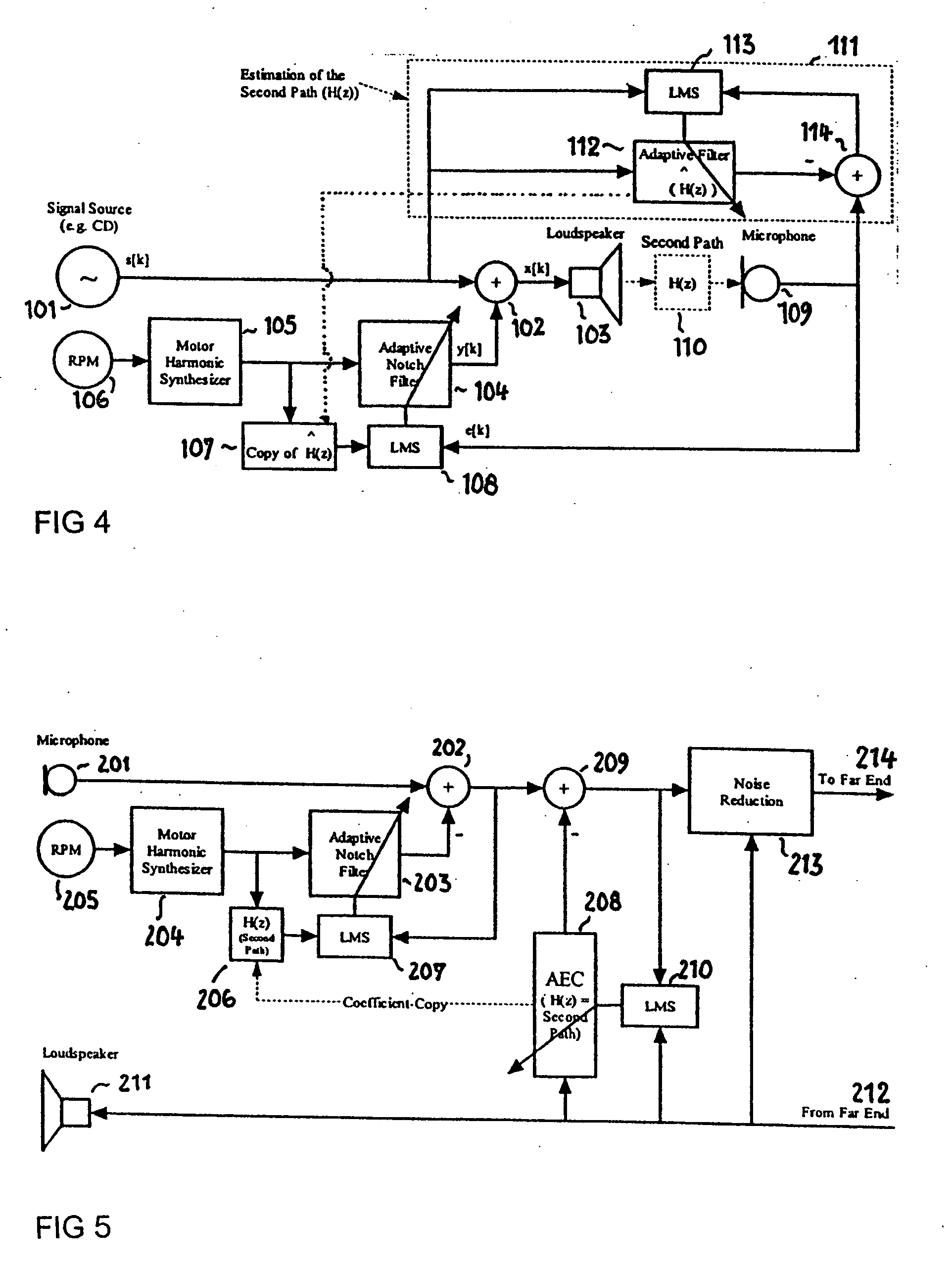
[0050] In FIG. 4, a signal s[k] from a signal source 101 is input to an adder 102. The adder 102 seems the signal s[k] and a signal y[k] that is generated by an adaptive notch filter 104. The resultant sum is output to a loudspeaker 103. The adaptive notch filter 104 receives its input signal from an engine harmonic synthesizer 105, which is controlled by a rotational speed sensor 106.

[0051] The engine harmonic synthesizer 105 generates a noise signal as a function of the rotational speed of the engine. This noise signal is input to a filter 107 having a dynamically adjustable transfer function H[z]. The output of the filter 107 is supplied to a control unit 108 which also receives a signal e[k] from a microphone 109.

[0052] The control unit 108 employs a least mean square (LMS) algorithm and controls the adaptive notch filter 104 so the output of the filter 107 is equal to the signal e[k]. The acoustic path between the loudspeaker 103 and the microphone 109, referred to as the sec...


PUM


Abstract

Active noise control system and method for controlling an acoustic noise generated by a noise source at a listening location, in which system and method sound is picked up in the surroundings of the listening location by a sound sensor; an electrical noise signal which corresponds to the acoustic noise of the noise source is generated and filtered adaptively in accordance with control signals. The adaptively filtered noise signal is irradiated into the surroundings of the listening location by a sound reproduction device, where a secondary path transfer function extends between the sound reproduction device and sound sensor. The noise signal is filtered with a transfer function that models the secondary path transfer function. The signals which provided by the sound sensor after first filtering serve as control signals for the adaptive filtering.

Description

CLAIM OF PRIORITY [0001] This patent application claims priority to European Patent Application serial number 04 006 433.9 filed on Mar. 17, 2004. FIELD OF THE INVENTION [0002] This invention relates to the field of signal processing, and in particular to an active noise tuning system. RELATED ART [0003] Systems for actively compensating noise (Active Noise Control Systems), in particular cabin noise in vehicles are known. There are known methods that compensate periodic signals (e.g., engine harmonics) and methods that are intended to reduce the level of broadband noise. While systems are known for compensating periodic noise signals that are related to the rotational speed there are already applicable implementations available, while broadband systems are not suitable for general applications owing to the very high computing capacity required. [0004] Active noise control systems attenuate undesired noise. Noise tuning systems, on the other hand, are intended to equalize specific i...

Claims


Application Information

Patent Timeline
IPC IPC(8): A61F11/06G10K11/16G10K11/178G10L21/0208H03B29/00
CPCG10K11/1788G10L21/0208G10K2210/30232G10K11/17883G10K11/17885G10K11/17817G10K11/17827G10K11/17823G10K11/17825G10K11/17854
Inventor CHRISTOPH, MARKUS
Owner HARMAN BECKER AUTOMOTIVE SYST
Why Eureka
Try Eureka