Method, system, and program for correcting the image quality of a moving image

Inactive Publication Date: 2005-09-22
FUJIFILM HLDG CORP +1
View PDF7 Cites 32 Cited by
  • Summary
  • Abstract
  • Description
  • Claims
  • Application Information

AI Technical Summary

Benefits of technology

[0010] In view of the aforementioned circumstances, it is a first object of the present invention to provide an image processing method, an image processing system, and an image processing program that are capable of calculating correction values for the picture frames of a moving image and reliably eliminating the flickering of a corrected moving image. A second object of the present invention is to provide an image processing method, an image processing system, and an image processing program which are capable of eliminating the flickering of a corrected moving image, and also suitably correcting a picture frame whose fluctuation in a temporal direction is great in the same scene, as well as a picture frame that becomes a cut point representing a switch from one scene to another.

Problems solved by technology

However, the picture frames of a moving image vary in a temporal direction and the feature quantities also vary, so if the still-image correcting method is performed on each of the picture frames, flickering of a corrected moving image comprising the corrected picture frames will occur.
Thus, the object correction value for the last picture frame of the scene-1 is unsuitable.
However, a method for smoothing variation of correction values, such as that disclosed in the aforementioned U.S. Patent Application Publication No. 20020145678, inhibits fluctuations only with respect to correction values, and can eliminate the flickering of correction values when a fluctuation in the temporal direction of a picture frame is slight, but cannot eliminate the flickering of a corrected moving image.
When these corrections are inappropriate, discontinuous corrections will have an adverse influence on the image quality of the moving image.
On the other hand, if it is decided that the picture frame B is not a cut point, and the average value of the correction values for the picture frames A, B, and C is used as an object correction value for the picture frame B, the image quality is not good because differences among the picture frame B and the picture frames A, C are not reflected.

Method used


Image

  • Method, system, and program for correcting the image quality of a moving image
  • Method, system, and program for correcting the image quality of a moving image
  • Method, system, and program for correcting the image quality of a moving image

Examples


first embodiment

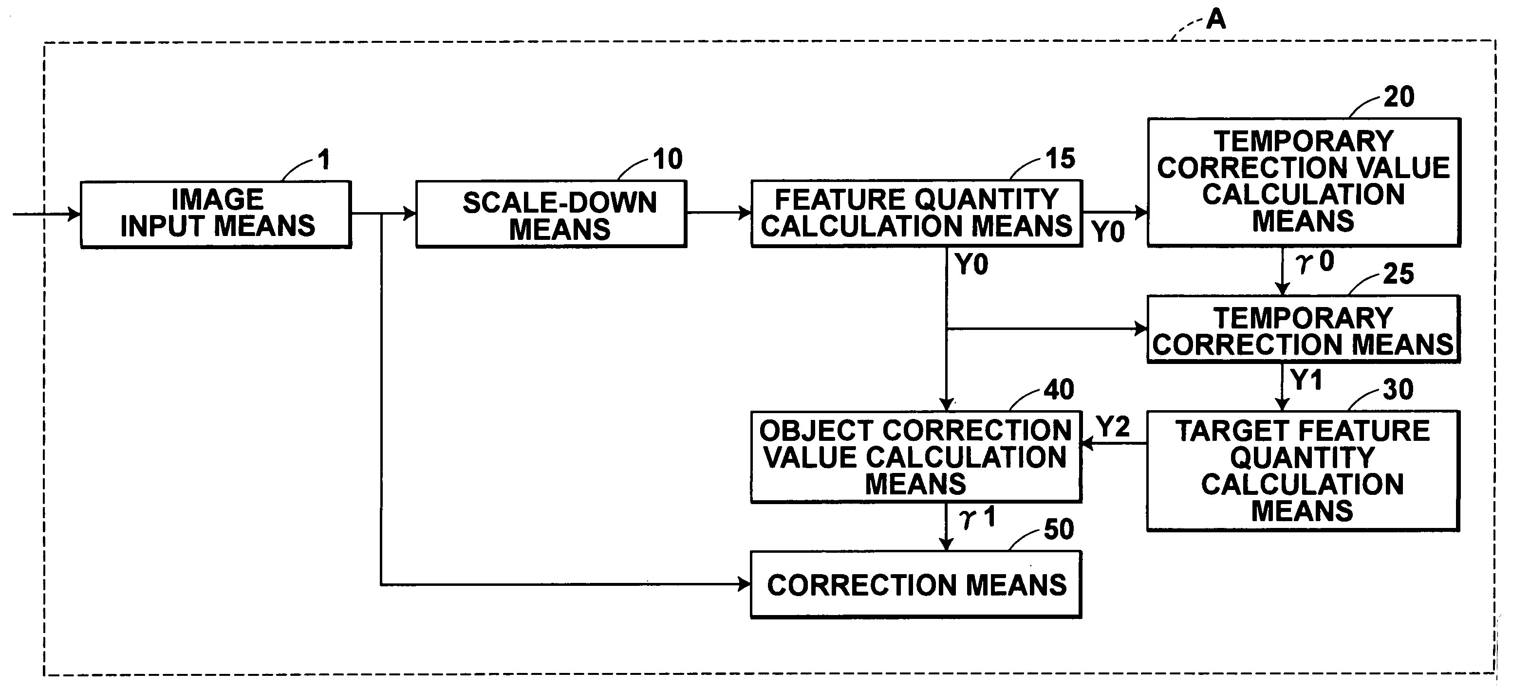
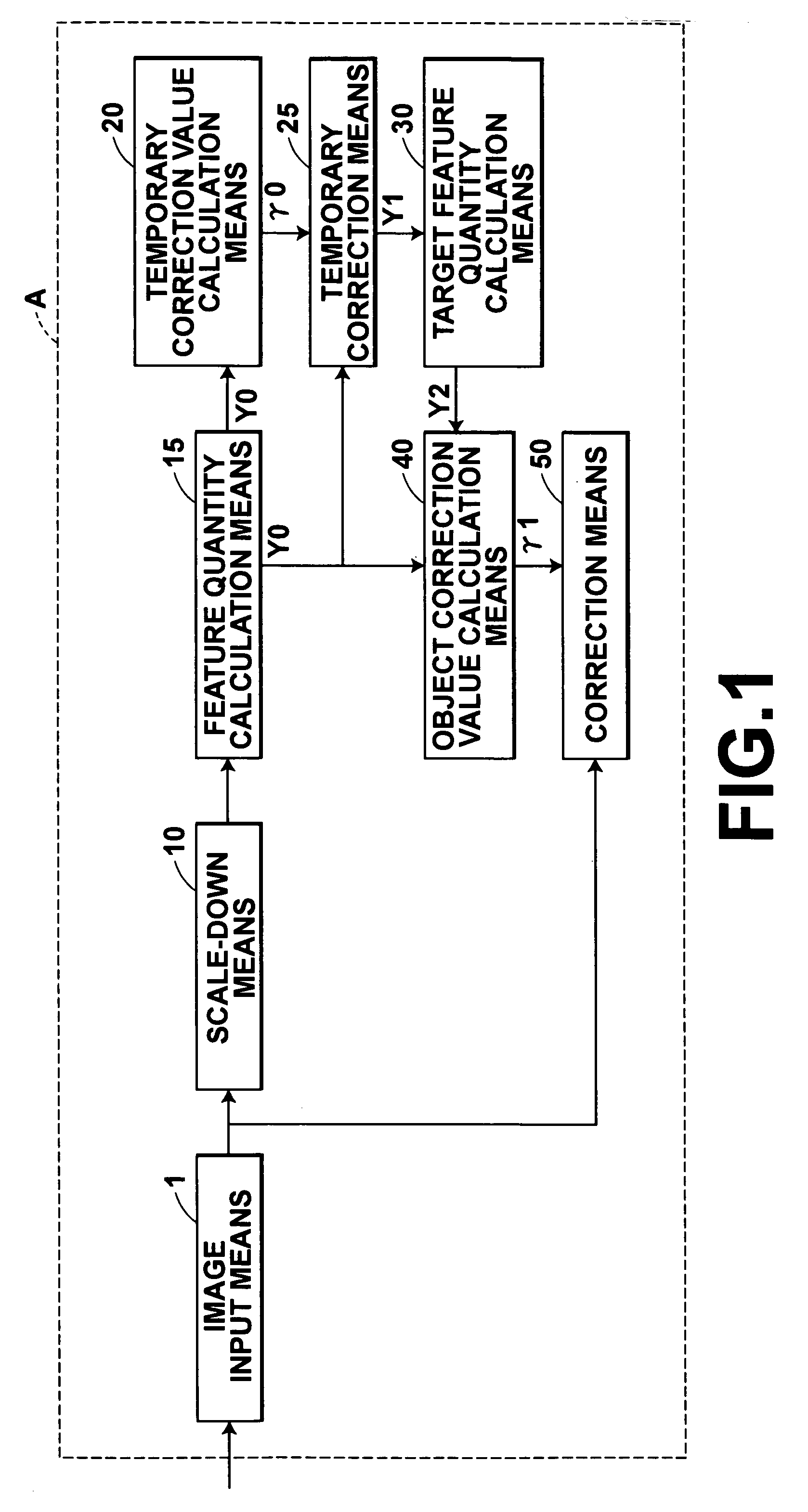
[0074] As shown in FIG. 1, the image processing system A of the first embodiment has eight major parts: (1) image input means 1 for acquiring a plurality of picture frames constituting a moving image; (2) scale-down means 10 for scaling down a picture frame and obtaining a thumbnail frame image; (3) feature quantity calculation means 15 for calculating a feature quantity of a thumbnail frame image, (4) temporary correction value calculation means 20 for calculating a temporary correction value using the feature quantity calculated by the feature quantity calculation means 15; (5) temporary correction means 25 for calculating a feature quantity of a temporarily corrected thumbnail frame image obtained by correcting a thumbnail frame image, using the temporary correction value calculated by the temporary correction value calculation means 20; (6) target feature quantity calculation means 30 for calculating a target feature quantity of each thumbnail frame image using the feature quant...

second embodiment

[0103] In the image processing system B, as shown in the figure, a picture frame obtained by the image input means 101 is scaled down by the scale-down means 110 and is obtained as a thumbnail frame image (S110 and S112). The feature quantity calculation means 115 calculates a feature quantity Y0 from each picture frame (S114). The reference picture frame selection means 118 first determines reference picture frames from the picture frames of the moving image. In the second embodiment, the reference picture frame selection means 118 selects reference picture frames by calculating the similarity, in the temporal direction, between picture frames and determining the interval between reference picture frames. The similarity can employ the correlation between picture frames. For example, the similarity can be made higher as the correlation becomes greater. If the determined interval between reference picture frames is n (where n is an integer ≧2), the first picture frame, the (n+1)st pi...

third embodiment

[0114] As shown in FIG. 7, the image processing system C of the third embodiment has five major parts: (1) image input means 201 for acquiring a plurality of picture frames constituting a moving image; (2) scale-down means 210 for scaling down a picture frame and obtaining a thumbnail frame image; (3) temporary correction value calculation means 220 for calculating a temporary correction value from the thumbnail frame image; (4) object correction value calculation means 240 for calculating an object correction value for a picture frame based on the temporary correction value calculated by the temporary correction value calculation means 220; and (5) correction means 250 for obtaining a corrected moving image by correcting each picture frame, using the object correction value calculated by the object correction value calculation means 240.

[0115] The temporary correction value calculation means 220 calculates a temporary correction value as follows. The temporary correction value calc...


PUM


Abstract

An image processing system has a scale-down section for scaling down frames of a moving image to obtain thumbnail images, a temporary correction value calculation section for calculating a temporary correction value by employing a first feature quantity calculated from the thumbnail image by a feature quantity calculation section, and a temporary correction section for calculating a second feature quantity of a temporarily corrected thumbnail image obtained by correcting each thumbnail image with the temporary correction value. The image processing system further has a target feature quantity calculation section for calculating a target feature quantity of each frame so that the second feature quantities vary smoothly in a temporal direction, an object correction value calculation section for calculating an object correction value so that the first feature quantity becomes the target feature quantity, and a correction section for obtaining a corrected moving image by correcting each frame with the object correction value.

Description

BACKGROUND OF THE INVENTION [0001] 1. Field of the Invention [0002] The present invention relates to image processing methods and systems for correcting the image quality of a moving image, and programs for carrying out the methods. [0003] 2. Description of the Related Art Correcting original digital images for image quality has been widely performed so that the digital images look attractive. Typical examples are white balance correction, exposure correction, color saturation correction, contrast correction, sharpness correction, color correction, etc. As a method of correcting a still image, it is a well known technique to extract a feature quantity from the still image, calculate a correction value based on the extracted feature quantity, and correct the original image with the correction value. The feature quantity to be extracted from a still image can employ an average luminance value for the original image, an average luminance value in a dark region within the original image...

Claims


Application Information

Patent Timeline
IPC IPC(8): G06K9/00G06K9/40G06T5/50
CPCG06T5/50
Inventor KAMEYAMA, HIROKAZU
Owner FUJIFILM HLDG CORP
Why Eureka
Try Eureka