

Releasable connection arrangement for two rotationally symmetrical components
- Summary
- Abstract
- Description
- Claims
- Application Information
AI Technical Summary
Benefits of technology
Problems solved by technology
Method used
Image

Examples
Embodiment Construction
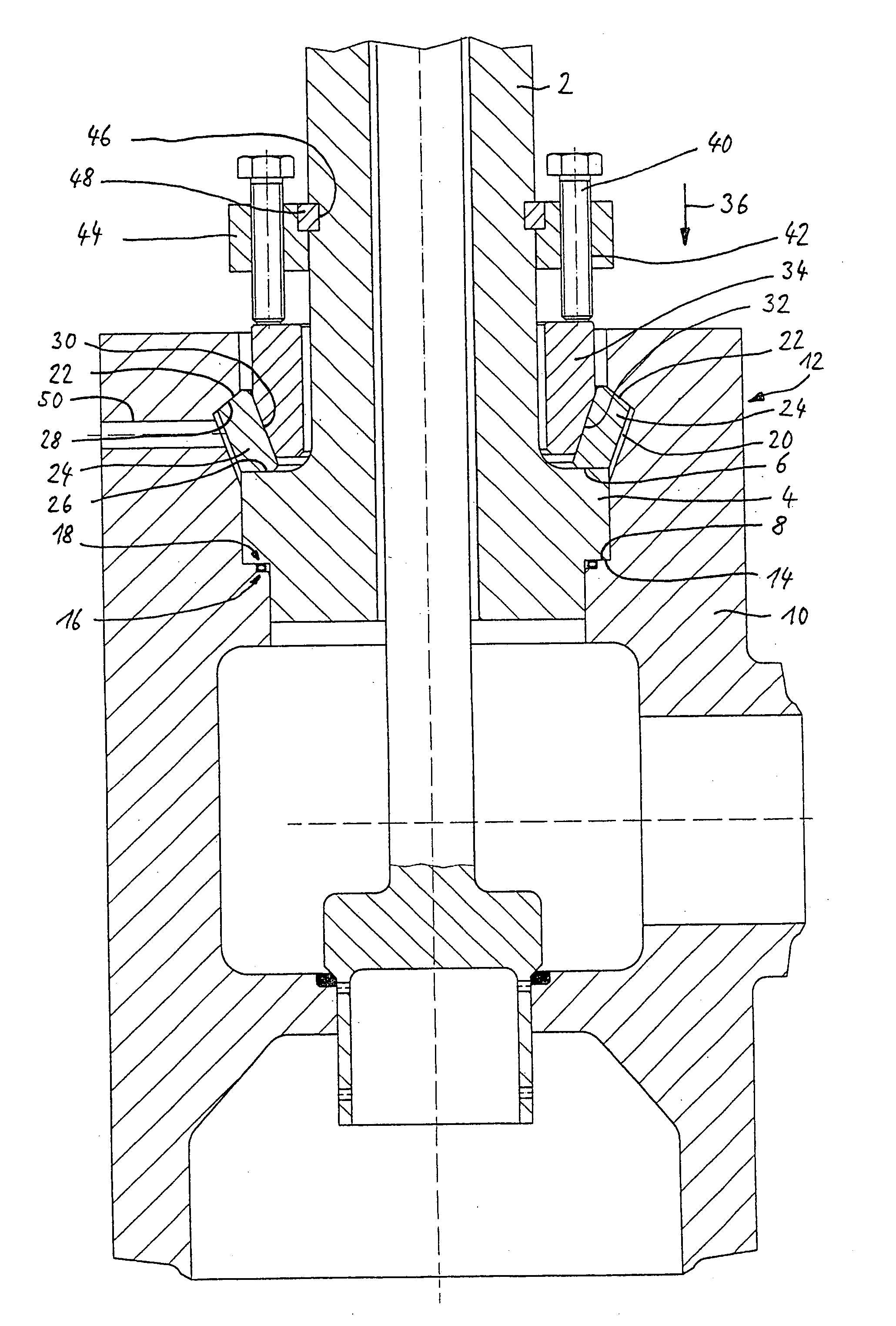
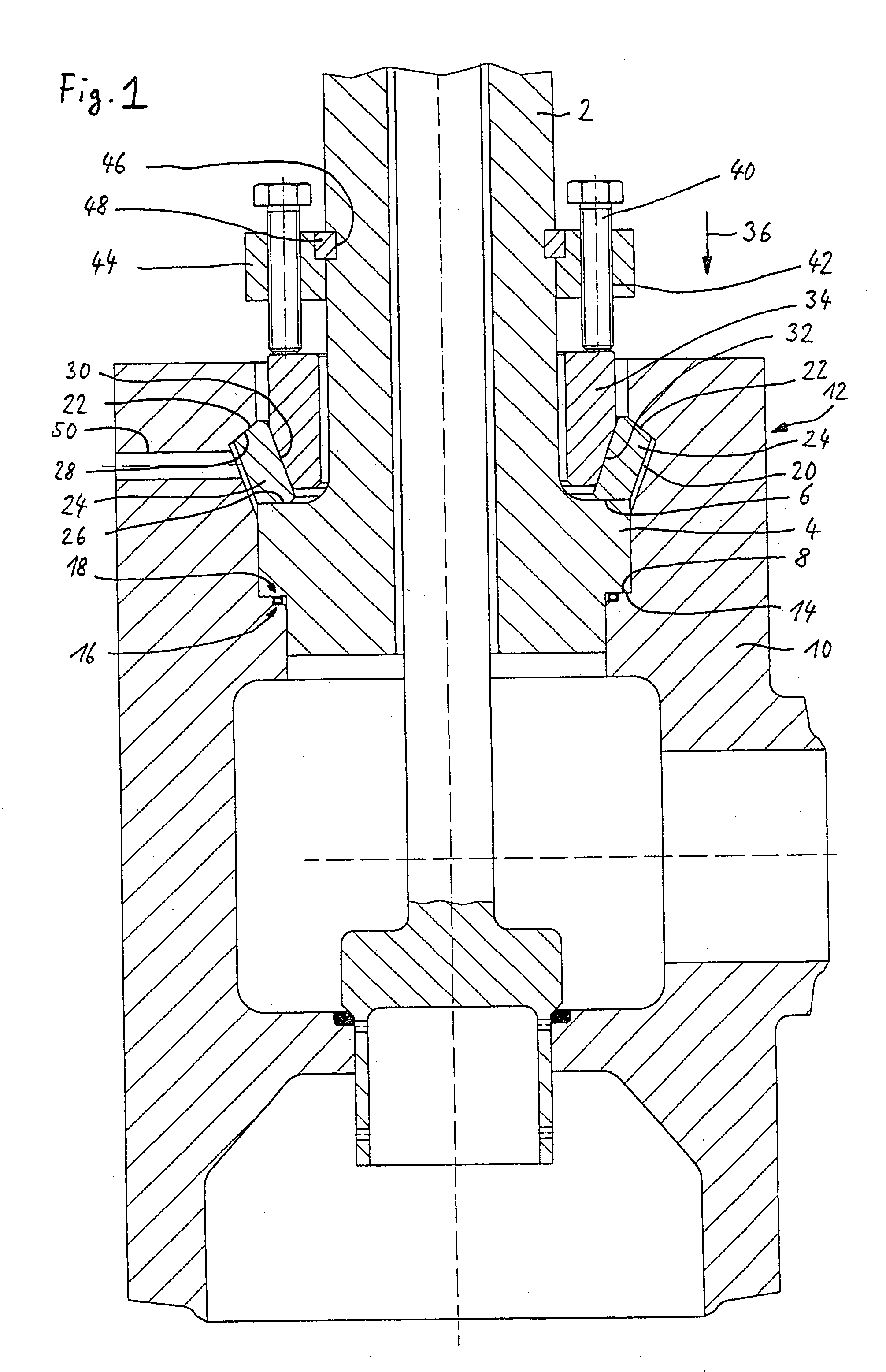
[0027] The invention will now be explained by reference to various embodiments relating to a novel cover lock of a power plant valve. In power plant valves for new conventional fossil-fuel thermal power plants, which are subject to high stresses, the operating pressures reach up to approx. 300 bar, while the operating temperatures can reach levels of 700° C. and more. The service lives of self-sealing graphite cover seals are not adequate in view of the extreme temperatures and pressures of the media. A graphite seal rapidly oxidizes to CO2 when an operating temperature of 500° C. is exceeded, permitting atmospheric oxygen to enter.
[0028] At operating temperatures on these levels, it is conceivable to use, among other things, a radially operative, high-temperature-resistant metal O-ring seal. From the structural point of view, the cover lock with a metal O-ring seal must be designed in such a way that the metal O-ring is placed in metal-to-metal contact. With conventional flange lo...
PUM
 Abstract
Description
Claims
Application Information