System for diagnosing reagent solution quality

a technology for diagnosing system and reagent solution, applied in the direction of exhaust treatment diagnostic device, digital computer details, amplifier modification to reduce noise influence, etc., can solve problems such as diagnostic circuit may produce fault values, illumination of fault lamps, and fault lamp illumination

Active Publication Date: 2005-09-22
CUMMINS FILTRATION IP INC
View PDF51 Cites 114 Cited by
  • Summary
  • Abstract
  • Description
  • Claims
  • Application Information

AI Technical Summary

Benefits of technology

[0005] The present invention may comprise one or more of the features recited in the attached claims and the following features and combinations thereof. A system for diagnosing the quality of a reagent solution may comprise a reagent solution source for supplying the reagent solution to an emissions catalyst of an internal combustion engine. Means may be provided for determining a quality value corresponding to the quality of the reagent solution. A filter may receive the quality value and produce a filtered quality value, and a comparator may compare the filtered quality value to a threshold and produce a fault value if the filtered quality value crosses the threshold. The filter may be a long-range averaging filter. The filter and the comparator may be implemented in the form of one or more software algorithms. The fault value may be logged in memory. Alternatively or additionally, the fault value may be transmitted by a wireless transceiver to a remote location. Alternatively or additionally, the fault value may trigger modification of engine performance by modifying engine fueling. Production of the fault value may alternatively or additionally result in illumination of a fault lamp. Alternatively or additionally, the fault value may be produced only after detection of a reagent solution refill event.
[0006] A system for diagnosing the quality of a reagent solution may comprise a reagent solution source for supplying the reagent solution to an emissions catalyst of an internal combustion engine. Means may be provided for determining a quality value corresponding to the quality of the reagent solution. A first filter may receive the quality value and produce a first filtered quality value. A second filter may receive the quality value and produce a second filtered quality value. A comparator may compare a difference between the first and second filtered quality values to a threshold and produce a fault value if the difference crosses the threshold. The first filter may be a long-range averaging filter, and the second filter may be a short-range averaging filter. The fault value may be logged in memory. Alternatively or additionally, the fault value may be transmitted by a wireless transceiver to a remote location. Alternatively or additionally, the fault value may trigger modification of engine performance by modifying engine fueling. Production of the fault value may alternatively or additionally result in illumination of a fault lamp. Alternatively or additionally, the fault value may be produced only after detection of a reagent solution refill event.
[0007] A system for diagnosing the quality of a reagent solution may comprise a reagent solution source for supplying the reagent solution to an emissions catalyst of an internal combustion engine. Means may be provided for determining a quality value corresponding to the quality of the reagent solution. A diagnostic circuit may process the quality value and produce a fault value if the quality of the reagent solution sufficiently deviates from an expected quality value. A temperature sensor may produce a temperature signal indicative of a temperat...

Problems solved by technology

Production of the fault value may alternatively or additionally result in illumination of a fault lamp.
A diagnostic circuit may process the quality value and pr...

Method used


Image

  • System for diagnosing reagent solution quality
  • System for diagnosing reagent solution quality
  • System for diagnosing reagent solution quality

Examples


Embodiment Construction

[0025] For the purposes of promoting an understanding of the principles of the invention, reference will now be made to a number of illustrative embodiments illustrated in the drawings and specific language will be used to describe the same.

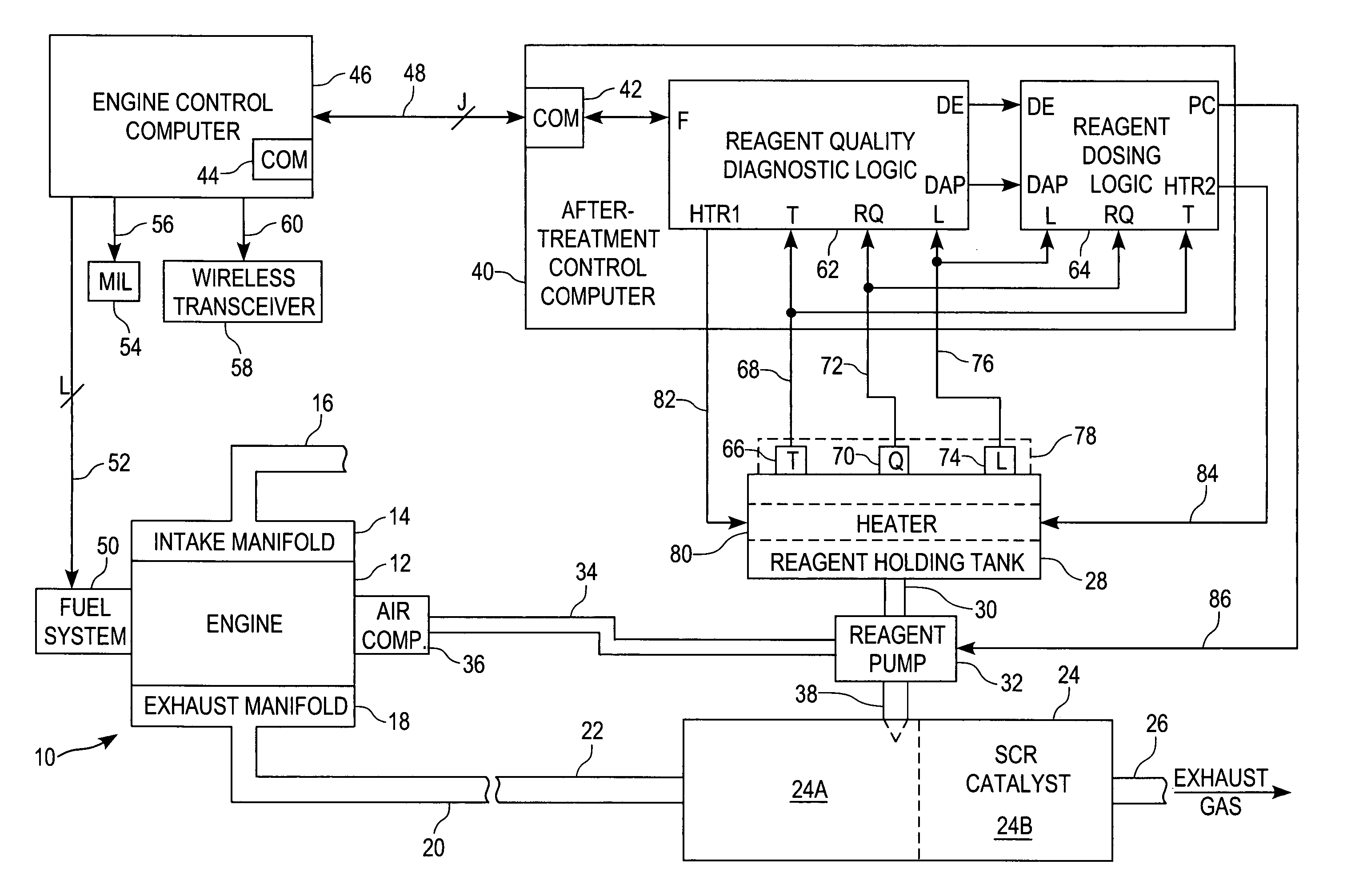
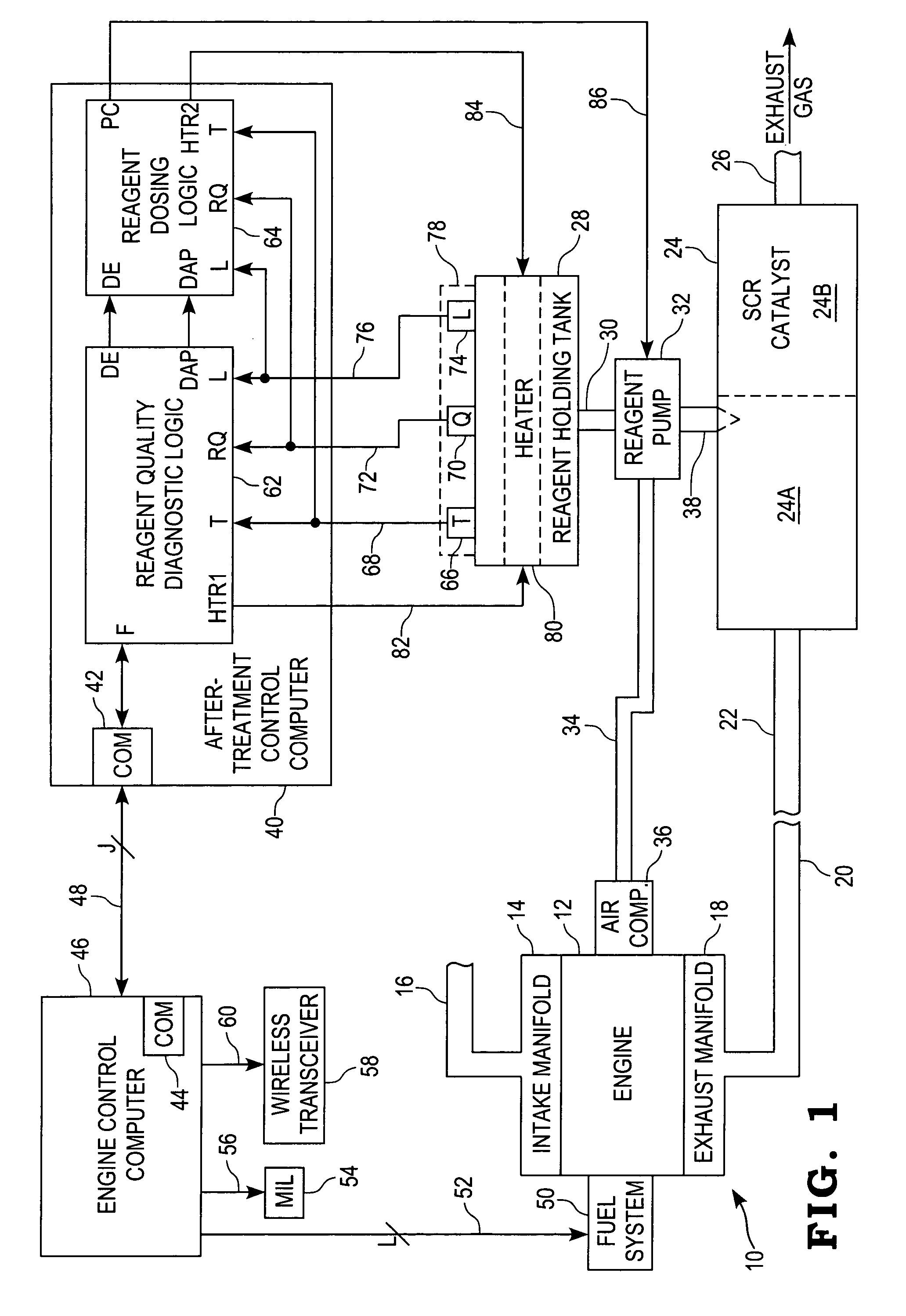
[0026] Referring now to FIG. 1, a block diagram is shown of one illustrative embodiment of a system 10 for diagnosing reagent solution quality. In the illustrated embodiment, system 10 includes an internal combustion engine 12 having an intake manifold 14 fluidly coupled to an intake pipe or conduit 16 for receiving fresh air. An exhaust manifold 18 of the engine 12 is fluidly coupled to an exhaust pipe or conduit 20, and exhaust gas resulting from the combustion process within the engine 12 is directed away from the exhaust manifold 18 via the exhaust pipe or conduit 20. Another exhaust pipe or conduit 22 is fluidly connected to an inlet of an emissions catalyst 24 having an outlet fluidly coupled to yet another exhaust pipe or conduit 26. In s...


PUM


Abstract

A system for diagnosing the quality of a reagent solution may comprise a reagent solution source for supplying the reagent solution to an emissions catalyst of an internal combustion engine. Means may be provided for determining a quality value corresponding to the quality of the reagent solution. A first filter may receive the quality value and produce a first filtered quality value, and a first comparator may compare the filtered quality value to a threshold and produce a fault value if the first filtered quality value crosses the threshold. Alternatively or additionally, a second filter may receive the quality value and produce a second filtered quality value. A second comparator may compare a difference between the first and second filtered quality values to another threshold and produce another fault value if the difference crosses that threshold.

Description

FIELD OF THE INVENTION [0001] The present invention relates generally to systems for diagnosing reagent solution quality, and more specifically to such systems producing a fault indicator if the reagent quality deviates sufficiently from an expected reagent quality. BACKGROUND OF THE INVENTION [0002] Systems for treating exhaust gas produced by an internal combustion engine to reduce exhaust gas emissions in the form of particulates and / or NOx are generally known. Such exhaust gas “aftertreatment” systems may include a selective catalytic reduction system for the purpose of reducing the NOx level of the exhaust gas below a specified maximum NOx level. [0003] A selective catalytic reduction system, or SCR, typically includes a catalytic reducing agent, or reagent, in the form of a reagent solution that is controllably dispensed into the exhaust gas stream produced by the engine before entering a conventional SCR catalyst. The SCR catalyst reacts with the combination of engine exhaust...

Claims


Application Information

Patent Timeline
IPC IPC(8): F01N3/08B01D53/94F01N3/20F01N11/00F02B37/00F02D41/02F02D41/22G01N33/00
CPCB01D53/9495Y02T10/24F01N3/208F01N11/00F01N2550/05F01N2570/14F01N2610/02F01N2610/08F01N2610/10F01N2610/1486F01N2900/0404F01N2900/0422F01N2900/1806F01N2900/1811F01N2900/1814F01N2900/1818F02B37/00F02D41/0235Y02T10/47B01D2257/404Y02T10/12Y02T10/40
Inventor BERRYHILL, ROSS C.WHITE, GREGORY R.
Owner CUMMINS FILTRATION IP INC
Why Eureka
Try Eureka