Internal die deckle with flow control

a technology of flow control and die slant, which is applied in the direction of dough shaping, manufacturing tools, food shaping, etc., can solve the problems of non-uniform coating thickness at the edges of the coated material, non-uniform thickness, and non-uniform molten resin, so as to improve the flow velocity and residence time of resin and improve the effect of fine adjustment resolution

Inactive Publication Date: 2005-09-22
EASTMAN KODAK CO
View PDF12 Cites 0 Cited by
  • Summary
  • Abstract
  • Description
  • Claims
  • Application Information

AI Technical Summary

Benefits of technology

[0007] The chamber is tapered axially to improve resin flow velocity and residence time. The slots adjust to control resin flow at an edge of the product. Together, the chamber and slots control resin flow to produce a uniform edge on the product. Interaction of the chamber and slots enable finer adjustment resolution than with die lip bolt adjustments. The slots are adjustable independently of product width changes.

Problems solved by technology

A common manufacturing problem resulting from the constant cross section internal and external deckles is non-uniform coating thickness at the edges of the coated material.
The non-uniformity of thickness can be caused by a number of factors such as non-uniform cavity pressure, non-uniform molten resin temperature, or non-uniform Theological properties.
In addition to multiple width limitations, resin flow rates and properties limit use of clothes hanger dies.
Constant cross section cavity extrusion dies are commonly constructed with adjustable lip sections to accommodate the cross width pressure distribution and resulting non-uniform resin flow.
Mechanical design constraints have limited cross width bolt adjustment intervals to approximately one inch.
Both of these items, bolt spacing and stiff sections, limit the usefulness of external die bolts to adequately provide the fine cross width resolution needed to control coating thickness at the edges.

Method used


Image

  • Internal die deckle with flow control
  • Internal die deckle with flow control
  • Internal die deckle with flow control

Examples


Embodiment Construction

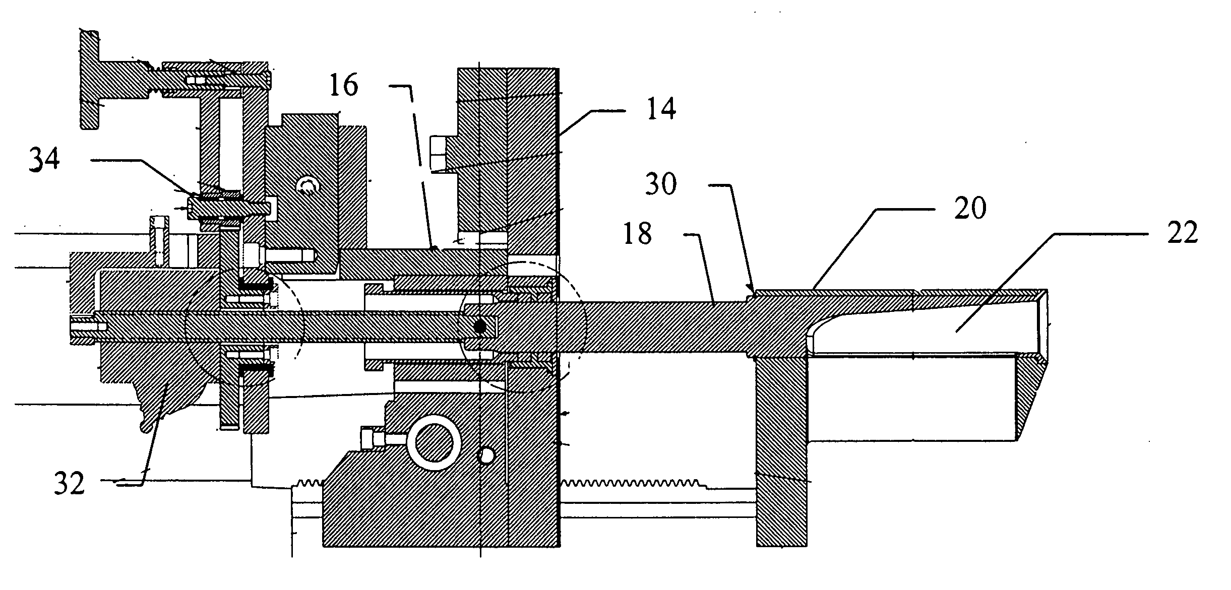
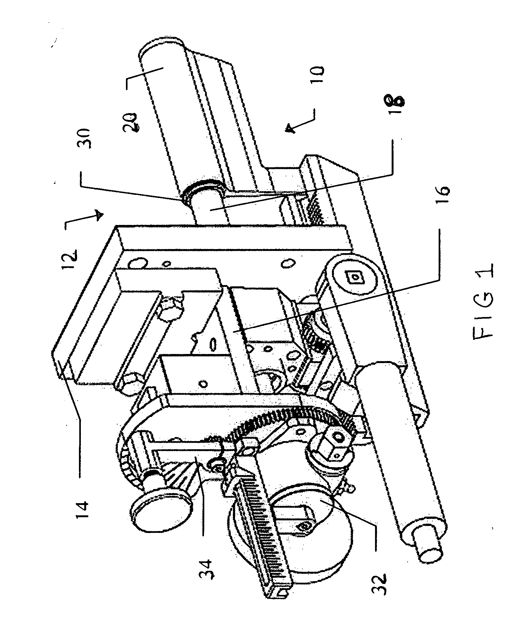
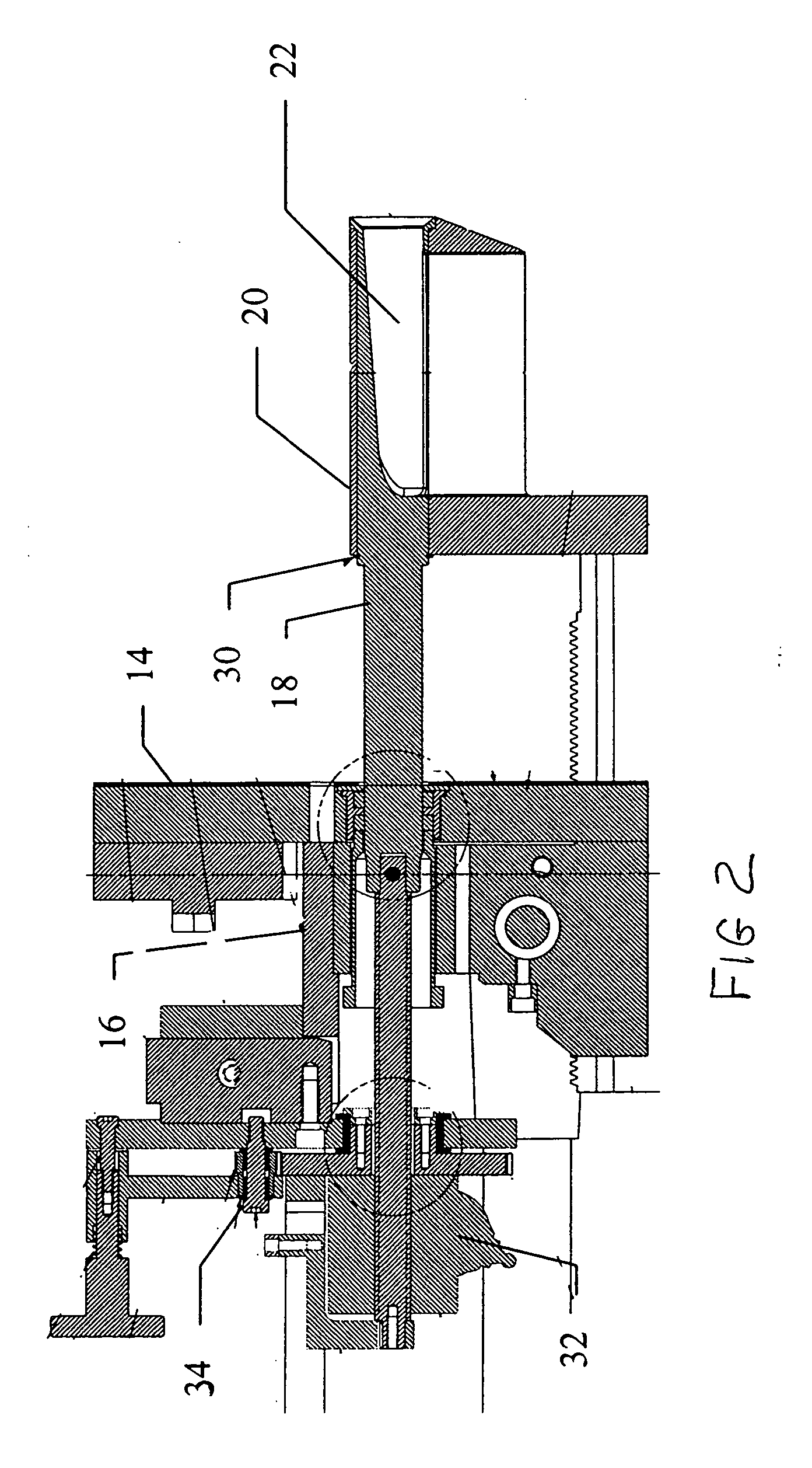
[0013] Referring to FIGS. 1-4, an apparatus 10 is illustrated for changing the width of an internal die cavity 12 to accommodate product width changes. The apparatus 10 illustrated effects only one edge of the product, it is to be understood that a second apparatus is required too at the other side edge of the product or material. The apparatus 10 includes a die end plate 14 having a front surface facing the internal die cavity 12, an opposed rear surface and defines an opening extending through the front and rear surfaces. An internal deckle mounting block 16 is attached to the rear surface of die end plate 14.

[0014] An internal deckle has a longitudinal axis, an inner deckle member 18 and an outer deckle member 20 and is mounted on mounting block 16. Inner deckle member 18 extends through the central opening of die plate 14 and defines a chamber 22 and a first longitudinal slot 24. Inner deckle member 18 has a first end portion engaging the mounting block 16 and is supported ther...


PUM

PropertyMeasurementUnit
cross widthaaaaaaaaaa
dimensionsaaaaaaaaaa
volumeaaaaaaaaaa

Abstract

An apparatus (10) for changing the width of an internal die cavity (12) to accommodate product width changes has a die end plate (14) with a front surface facing the internal die cavity (12), a rear surface and defines an opening that extends through the front and rear surfaces. An internal deckle mounting block (16) attaches to the rear surface of end plate (14). An internal deckle has inner (18) and outer (20) members and mounts on the mounting block (16). Inner member (18) extends through the opening of the die end plate (14) and defines a chamber (22) and a first longitudinal slot (24). The outer member (20) is positioned about the inner member (18) concentric therewith and defines a second longitudinal slot (26). The inner member (18) rotates about the outer member (20) to vary alignment of the slots and create a passageway narrower than either slot to control coating thickness.

Description

FIELD OF THE INVENTION [0001] The invention relates generally to extrusion coating of polymeric resins using a coating die, and more particularly to a device for controlling the flow of resin at the edges of an extrusion coating die. BACKGROUND OF THE INVENTION [0002] Polymeric resins are extrusion coated through dies to produce a polymeric coating. In producing photographic paper, a polymeric resin, such as polyethylene for example, is extrusion coated through dies onto the photographic paper substrate. The internal cavity of the die is normally of constant cross section across the coating width thereby enabling manufacture of various coating widths using a single die. Typically, coating width changes are made by adjusting external deckles which restrict the flow of resin through the slot opening. A common manufacturing problem resulting from the constant cross section internal and external deckles is non-uniform coating thickness at the edges of the coated material. The non-unifor...

Claims


Application Information

Patent Timeline
Patent Type & Authority Applications(United States)
IPC IPC(8): B29C48/31B05C5/02B29C48/92
CPCB05C5/0258B05C5/0262B05C5/0266B29C47/0009B29C2947/92514B29C47/92B29C2947/92628B29C2947/92647B29C2947/92704B29C2947/92857B29C2947/926B29C48/03B29C48/92B29C2948/92514B29C2948/926B29C2948/92628B29C2948/92647B29C2948/92704B29C2948/92857
Inventor BOMBA, RICHARD D.
Owner EASTMAN KODAK CO
Why Eureka
Try Eureka