Orbital atherectomy device guide wire design

a technology for orbital atherectomy and guide wires, which is applied in the field of medical devices, can solve the problems of bending failure of ptfe tubing, premature failure of oad and/or guide wires, and segment difficulty in extraction, so as to reduce the trauma to the vessels, reduce trauma, and reduce the effect of trauma

Inactive Publication Date: 2005-09-22
CARDIOVASCULAR SYST INC
View PDF12 Cites 65 Cited by
  • Summary
  • Abstract
  • Description
  • Claims
  • Application Information

AI Technical Summary

Benefits of technology

[0011] A guide wire for assisting in implantation and balancing of an orbital atherectomy device is disclosed. The guide wire is generally configured to be received within a driveshaft and cutting region of the orbital atherectomy device. The guide wire is sufficiently flexible to minimize trauma to the vessel walls is positioned within a patient. The distal end of the guide wire can include on or more weighted elements movabl

Problems solved by technology

Further, the contact of the OAD driveshaft with the flexible PTFE tubing has been found to cause torsion and bending failure of the PTFE tubing with the failed segment difficult to extract.
In addition, the rotati

Method used


Image

  • Orbital atherectomy device guide wire design
  • Orbital atherectomy device guide wire design
  • Orbital atherectomy device guide wire design

Examples


Embodiment Construction

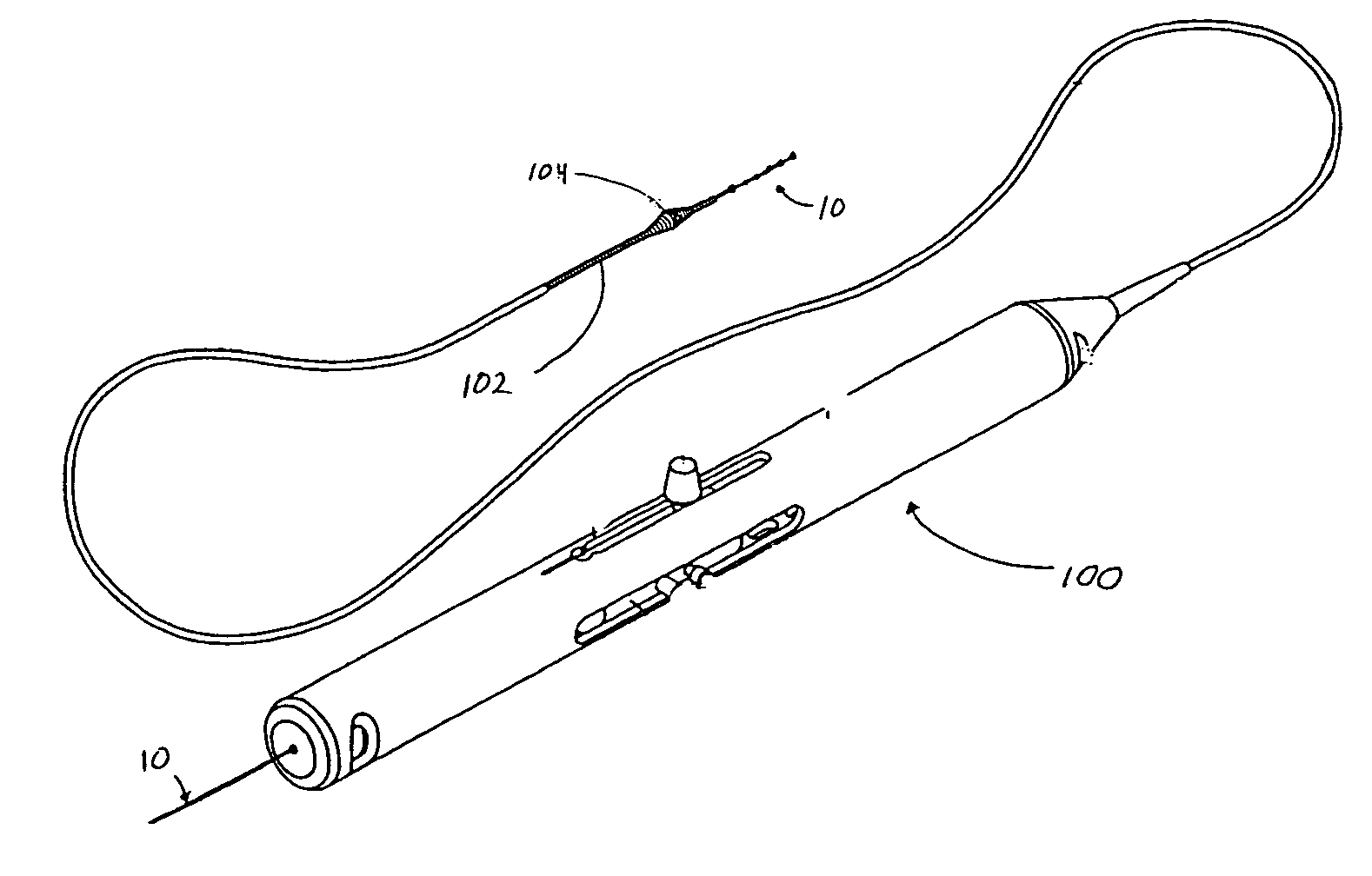
[0018] The present invention relates to a novel design for a guide wire that is generally illustrated throughout the figures as guide wire 10. The figures illustrate the guide wire 10 in particular embodiments and, in some figures, in conjunction with particular medical devices for ease of description and understanding. The figures are not intended to limit the possible applications of the present invention. The scope of the invention will be defined by the claims and will be understood by those skilled in the art upon review of the specification and figures.

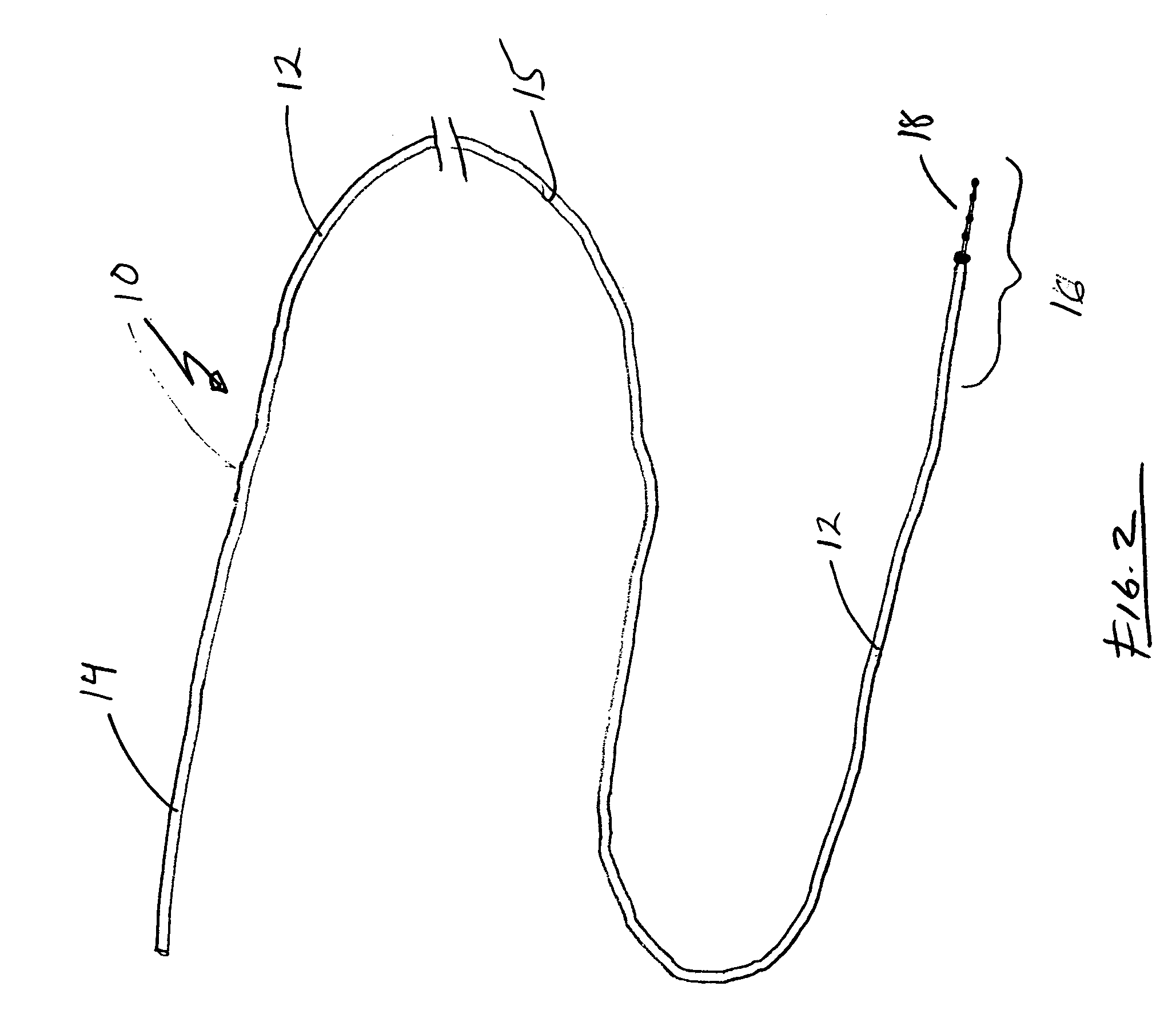
[0019] Turning to FIG. 2, guide wire 10 is generally configured to permit distal region 16 of guide wire 10 to be positioned, relatively atraumatically, at a desired location within a patient. Accordingly, guide wire 10 is flexible and includes an atraumatic tip 18 to prevent damage to tissues as the guide wire is advanced.

[0020] Guide wire 10 generally includes an elongated shaft 12 having a proximal region 14, a central regi...


PUM


Abstract

A guide wire for assisting in implantation and balancing of an orbital atherectomy device is disclosed. The guide wire is generally configured to be received within a driveshaft and cutting region of the orbital atherectomy device. The guide wire is sufficiently flexible to minimize trauma to the vessel walls is positioned within a patient. The distal end of the guide wire can include on or more weighted elements movable along the distal region of the guide wire to permit the balancing of an a rotating drive shaft and cutting region of an orbital atherectomy device. The guide wire can also include an atraumatic tip located on the end of the guide wire to reduce trauma to the vessels during implantation. Lubricious coatings are also provided to reduce friction between the driveshaft and cutting region of the atherectomy device and guide wire.

Description

[0001] This is a continuation-in-part of U.S. patent application filed Jan. 7, 2004 and titled TERMINAL GUIDE FOR ROTATIONAL ATHERECTOMY DEVICE AND METHOD OF USING SAME.BACKGROUND OF THE INVENTION [0002] The present invention relates to medical devices and, more particularly, to guide wires for positioning and stabilization of intravascular medical devices. [0003] Atherectomy devices are generally designed to remove stenotic occlusions from human arteries and bypass grafts. Atherectomy devices take a number of forms from mechanical cutting devices to various rotating abrading device. [0004] The OAD consists of three stainless steel wires, helically wound to produce a device driveshaft. The OAD has an expanded, eccentric cross-section with an attached diamond surface “crown” located near the distal end. The OAD is revolved at rotational velocities up to 200,000 rpm, with the “crown's” abrasive surface removing stenotic tissue. The Orbital Atherectomy Device is deployed along and rota...

Claims


Application Information

Patent Timeline
IPC IPC(8): A61B17/00A61B17/22A61B17/32A61B19/00
CPCA61B17/320758A61B2017/0084A61B2019/303A61B2017/320004A61B2017/320766A61B2017/22042A61B2090/033
Inventor PRUDNIKOV, DMITRIYBORGERSEN, SVENN EDVIN
Owner CARDIOVASCULAR SYST INC
Why Eureka
Try Eureka