Machining configuration drawing apparatus and machining configuration drawing method

a technology of configuration drawing and machining, applied in the direction of computer control, program control, instruments, etc., can solve the problems of deteriorating operation efficiency, difficult to confirm details, difficult to confirm a present machining position, etc., to prevent excessive change of display magnification, reduce processing workload, and reduce the effect of arithmetic operation

Active Publication Date: 2005-09-22
FANUC LTD
View PDF6 Cites 3 Cited by
  • Summary
  • Abstract
  • Description
  • Claims
  • Application Information

AI Technical Summary

Benefits of technology

[0026] According to the present invention, when the machining configuration of the wire electric discharge machine is drawn, the arithmetic operation, which is otherwise necessary to calculate a display magnification and to set a drawing region based on the calculated display magnification, can be made unnecessary by previously setting the size of the display area, thereby the processing amount of the arithmetic operation and a setting workload can be reduced.
[0027] Since the drawing region is determined using the size of the previously set display area, the display magnification is made definite. Accordingly, the display magnification can be prevented from being excessively changed, thereby a present machining position can be easily confirmed on a screen.
[0028] Further, since the display area can be arbitrarily set by an operator, the display magnification can be easily set for each operator and for each machining.

Problems solved by technology

An operation for setting and displaying the enlarged display area again imposes a burden on an operator in addition to an operation for machining, due to which an operating efficiency is deteriorated.
However, since the resolution of display on the screen is lowered thereby, the present machining position and the machining configuration are displayed in a small size, which makes it difficult to confirm details.
Accordingly, a problem arises in that it is difficult to confirm a present machining position because the display magnification is changed frequently, in addition to a problem that an amount of calculation processing is increased.
The display area update method is disadvantageous in that a setting workload is increased because the partial machining regions must be previously set.
Further, since display magnifications are previously set as a program or items to be set, a problem arises in that it is difficult to set the display magnifications for each operator or for each machining.

Method used


Image

  • Machining configuration drawing apparatus and machining configuration drawing method
  • Machining configuration drawing apparatus and machining configuration drawing method
  • Machining configuration drawing apparatus and machining configuration drawing method

Examples


first embodiment

[0046] A first embodiment of the machining configuration drawing apparatus of the present invention will be explained below with reference to FIGS. 2 to 8. According to the first embodiment, an overall drawing region is previously divided into a plurality of drawing regions, and a divided drawing region is selected according to a present machining position and displayed.

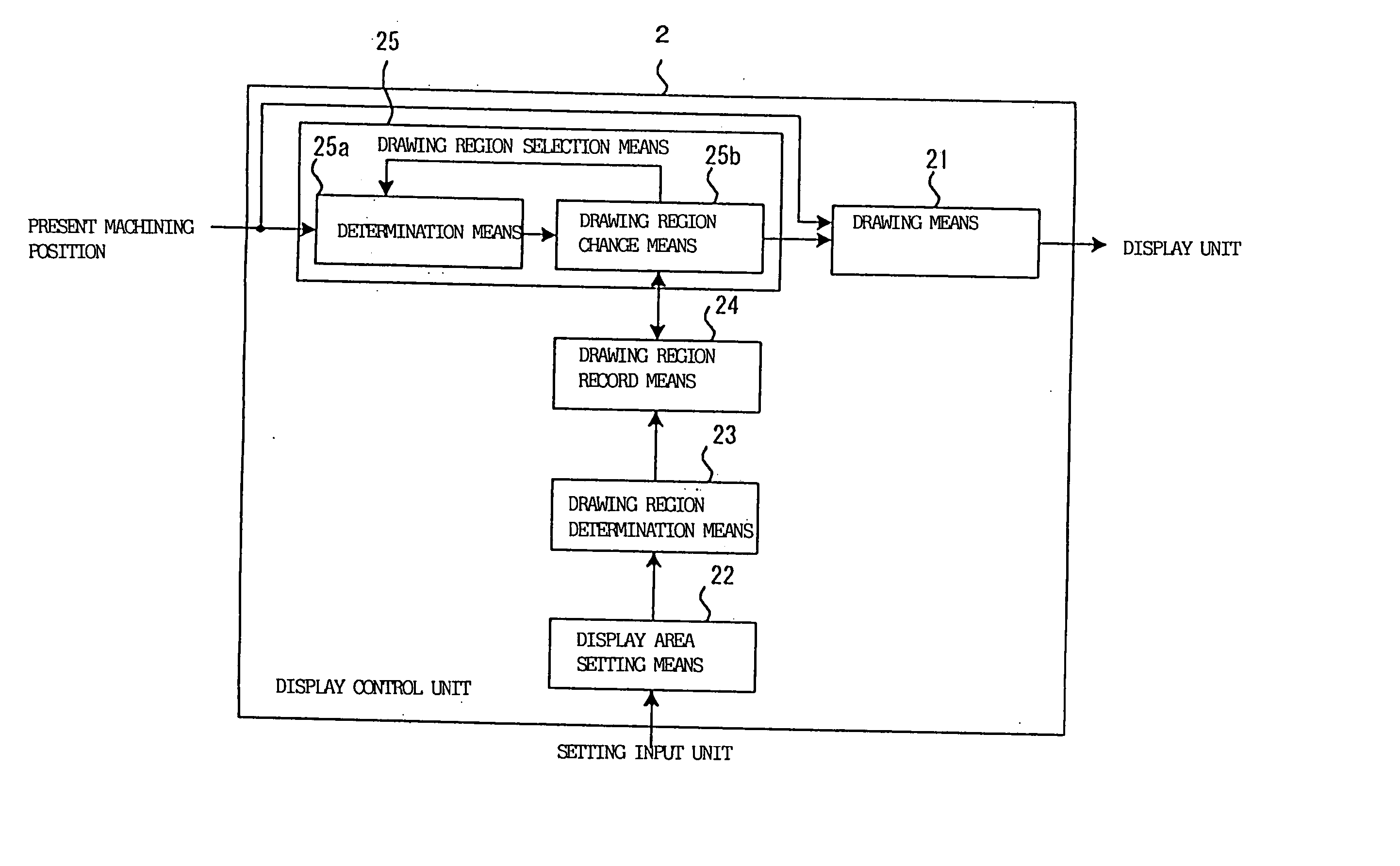
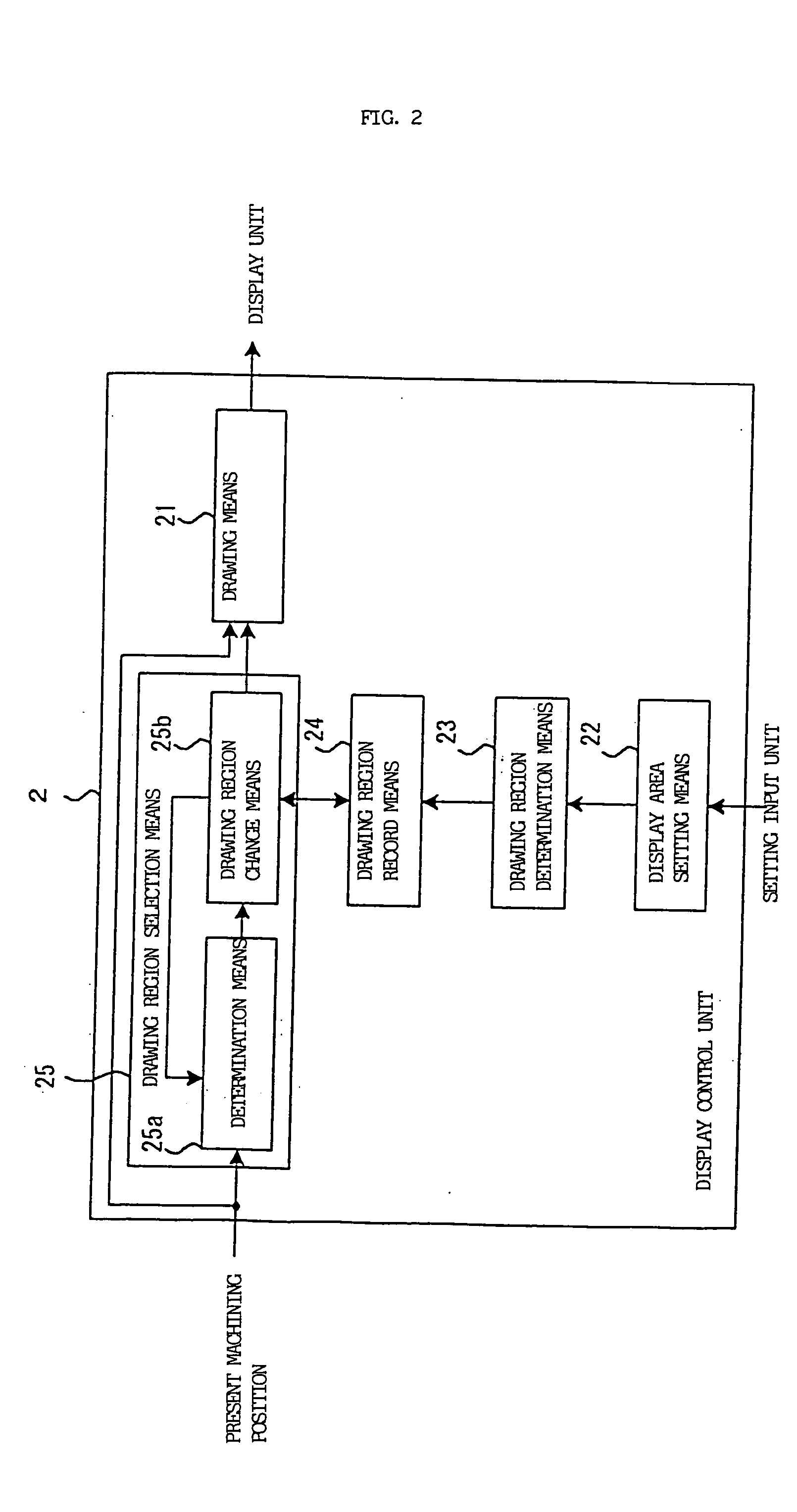
[0047]FIG. 2 shows an example of a display control unit 2 of the machining configuration drawing apparatus of the first embodiment. In FIG. 2, the display control unit 2 includes a drawing means 21, a display area setting means 22, a drawing region determination means 23, a drawing region record means 24, and a drawing region selection means 25. The drawing means 21 draws a machining configuration and a present machining position and causes a display unit 3 to display them thereon, the display area setting means 22 sets a display area in an overall drawing area, the drawing region determination means 23 divides the ...

second embodiment

[0071] A second embodiment of the machining configuration drawing apparatus of the present invention will be explained below with reference to FIGS. 9 to 13. According to the second embodiment, a drawing region is determined and displayed such that a predetermined position (central position) in the drawing region coincides with a present position at all times.

[0072]FIG. 9 is an example of a display control unit 2 included in the machining configuration drawing apparatus of the embodiment. In FIG. 9, the display control unit 2 includes a drawing means 21, a display area setting means 22, a drawing region creation means 27, and a position monitor means 28. The drawing means 21 draws a machining configuration and a present machining position, the display area setting means 22 sets a display area in an overall drawing area, the drawing region creation means 27 creates a drawing region drawn by the drawing means 21 in the overall drawing area, and the position monitor means 28 monitors ...


PUM

PropertyMeasurementUnit
lengthsaaaaaaaaaa
lengthaaaaaaaaaa
areaaaaaaaaaaa

Abstract

A machining configuration drawing apparatus includes a drawing unit for drawing a machining configuration and a present machining position, a setting unit for setting a display area in an overall drawing area, a division unit for dividing the overall drawing area into a plurality of display areas based on the set display area, and a selection unit for selecting a drawing region drawn by the drawing unit from a plurality of drawing regions. The selection unit selects a drawing region in which the present machining position exists. Further, the drawing unit draws a machining configuration and a present machining position of the selected drawing region.

Description

BACKGROUND OF THE INVENTION [0001] 1. Field of the Invention [0002] The present invention relates to drawing of a machining configuration, and more particularly, to a drawing apparatus for and a drawing method of displaying a machining configuration in an electric discharge machine. [0003] 2. Description of the Related Art [0004] In wire electric discharge machines, a machining configuration is drawn on a screen to confirm the contents of a machining program and a present machining position. [0005] When the machining configuration is displayed on the screen, a part of a machining path may be displayed thereon in enlargement to confirm the detailed configuration of a present machining position depending on a configuration and a size to be machined, in addition to the case where an overall machining configuration is displayed on the screen. [0006] When a part of the machining path is displayed, the present machining position may run off the machining path on the screen on which the pr...

Claims


Application Information

Patent Timeline
Patent Type & Authority Applications(United States)
IPC IPC(8): B23Q15/00B23H1/02B23H7/26G05B19/4068G05B19/4069
CPCG05B2219/35351G05B19/4068B23H7/06B23H7/20
Inventor OGATA, TOSHIYUKISUZUKI, KOJIABE, HIROYUKI
Owner FANUC LTD
Why Eureka
Try Eureka