Doppler ultrasonic flowmeter, and processor and method thereof with quantization error correction

a technology of ultrasonic flowmeter and processor, which is applied in the direction of liquid/fluent solid measurement, instruments, machines/engines, etc., and can solve problems such as measurement errors

Active Publication Date: 2005-09-22
FUJI ELECTRIC CO LTD
View PDF4 Cites 30 Cited by
  • Summary
  • Abstract
  • Description
  • Claims
  • Application Information

AI Technical Summary

Problems solved by technology

The quantization error, however, generally occurs to the spatial resolution, which

Method used


Image

  • Doppler ultrasonic flowmeter, and processor and method thereof with quantization error correction
  • Doppler ultrasonic flowmeter, and processor and method thereof with quantization error correction
  • Doppler ultrasonic flowmeter, and processor and method thereof with quantization error correction

Examples


Embodiment Construction

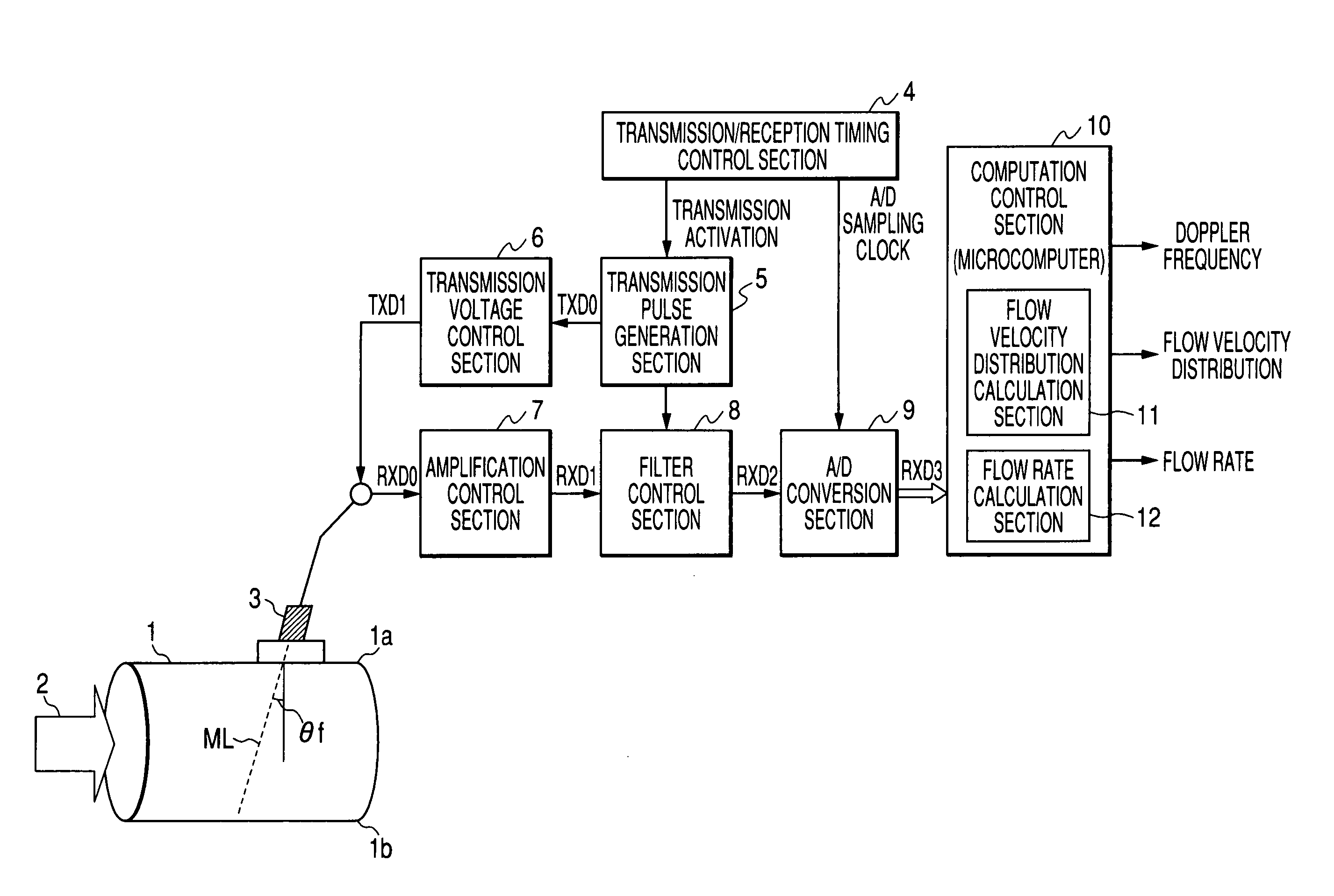
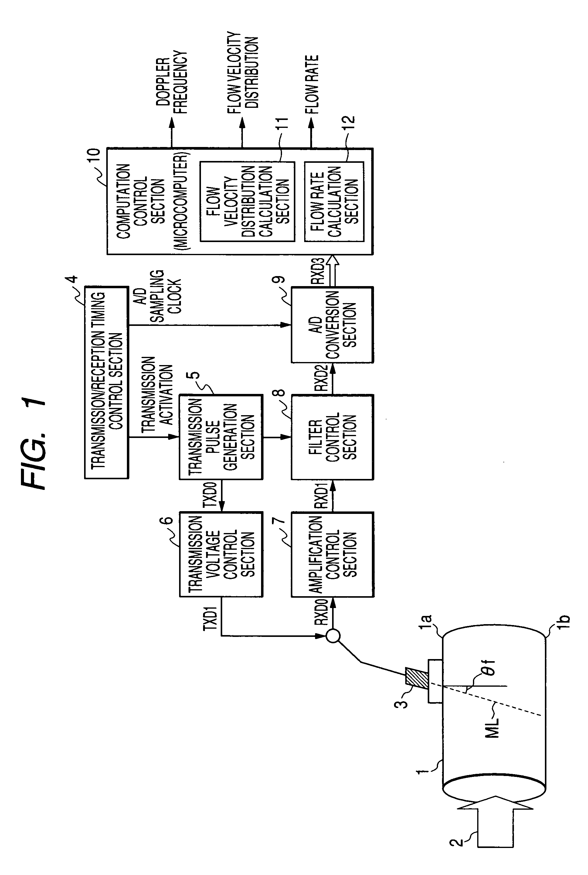
[0024] Referring to FIG. 1, the present Doppler ultrasonic flowmeter includes an ultrasonic transducer 3, a transmission / reception timing control section 4, a transmission pulse generation section 5, a transmission voltage control section 6, an amplification control section 7, a filter control section 8, an A / D conversion section 9, and a computation control section 10. The computation control section 10 can be a microcomputer (CPU / MPU), and includes a flow velocity distribution calculation section 11, and a flow rate calculation section 12.

[0025] Hereafter, the above-described components, i.e., the ultrasonic transducer 3, the transmission / reception timing control section 4, the transmission pulse generation section 5, the transmission voltage control section 6, the amplification control section 7, the filter control section 8, and the A / D conversion section 9, are collectively referred to as an ultrasonic wave transmission / reception section. As will be described below, the ultras...


PUM


Abstract

In a Doppler ultrasonic flowmeter, to obtain a precise flow rate a flow rate calculation equation that corrects a quantization error occurring to a spatial resolution is used. An ultrasonic transducer transmits/receives ultrasonic pulses, and subject the resulting received signals to A/D conversion after a predetermined process is applied thereto. A computation control section calculates the flow velocity distribution. Then, the flow rate is calculated based on the flow rate calculation equation, which corrects the quantization error occurring to the spatial resolution.

Description

BACKGROUND [0001] A clamp-on ultrasonic flowmeter is a type that measures, from outside of a tubular body, such as a water pipe, the flow velocity and the flow rate of fluid flowing inside the tubular body with an ultrasonic transducer (module for transmitting / receiving ultrasonic pulses of arbitrary frequency) attached to part of the outer surface of the tubular body. The clamp-on ultrasonic flowmeter is roughly classified into a transit time type and a Doppler type. [0002] The transit time type uses a technique in which ultrasonic waves are made to go back and forth on a path that crosses diagonally over the fluid flowing inside a tubular body. The flow rate of the fluid is measured from the difference of time taken for the ultrasonic waves to transit the outward path and the return path, respectively. [0003] On the other hand, the Doppler type use a technique in which suspended particles, air bubbles, or other flaws included in the fluid are presumed to move at the same speed as ...

Claims


Application Information

Patent Timeline
IPC IPC(8): G01F1/66G01P5/00
CPCG01F1/663
Inventor YAMADA, KAZUYUKIOHMURO, YOSHINORIHIRAYAMA, NORITOMOKISHIRO, MASAMI
Owner FUJI ELECTRIC CO LTD
Why Eureka
Try Eureka