

Optimization method and optimization apparatus
a technology of optimization apparatus and optimization method, which is applied in the direction of electric/magnetic computing, instruments, computing models, etc., can solve the problems of not being able to solve the solution of a constrained optimization problem by such a simple algorithm, not being able to select the penalty function, and not being able to solve the problem as easy, so as to achieve the effect of solving a constrained optimization problem
- Summary
- Abstract
- Description
- Claims
- Application Information
AI Technical Summary
Benefits of technology
Problems solved by technology
Method used
Image

Examples
first embodiment
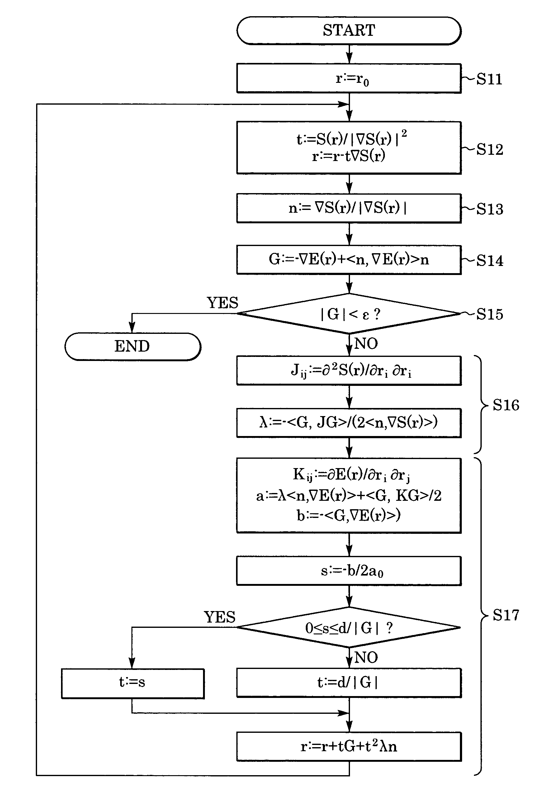
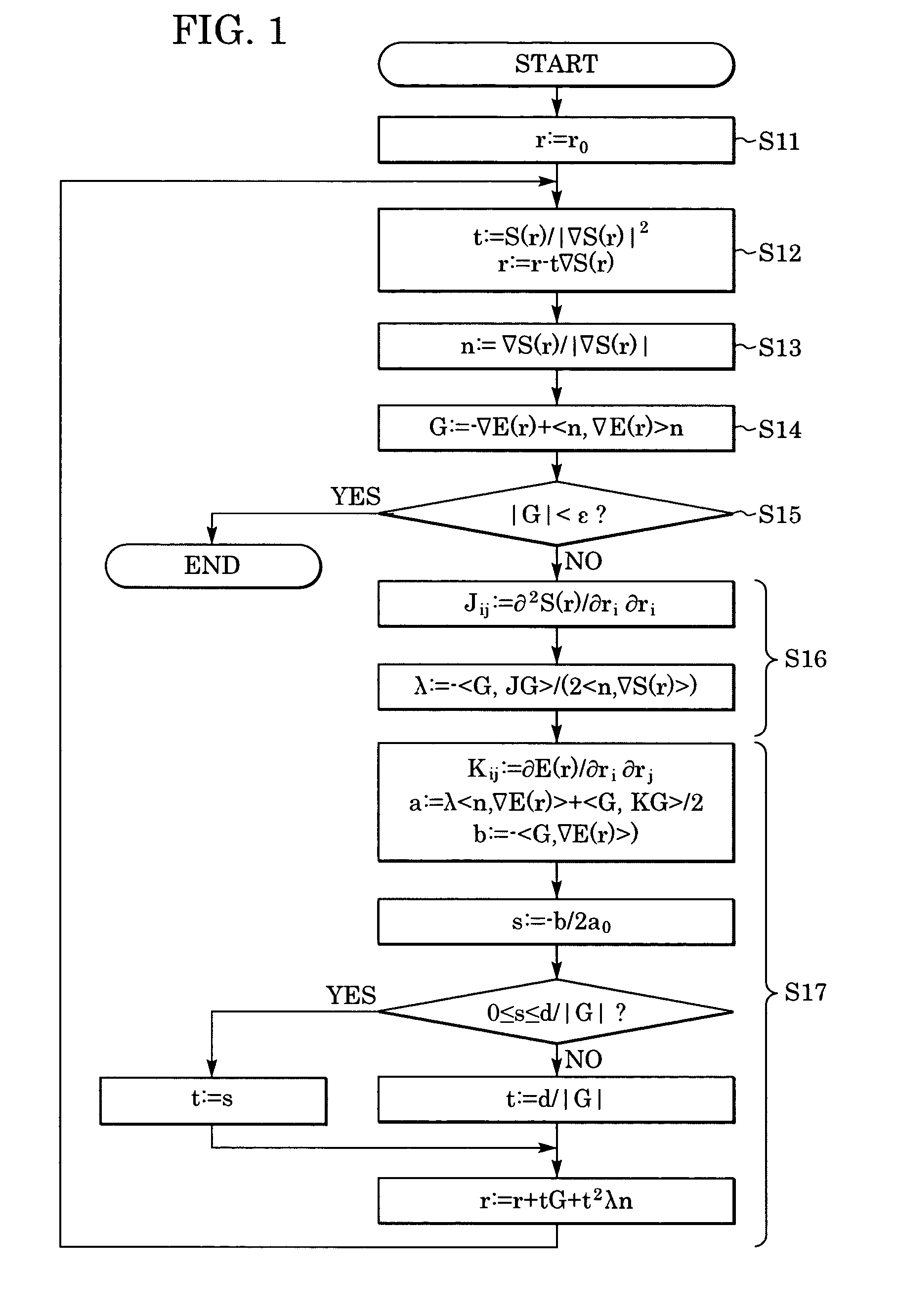
[0030] The method for optimization according to this embodiment includes two steps: linearly approaching the hypersurface S(r)=0 and finding an extreme value along a curved line having second-order osculation in the projection direction of the gradient vector of the plane tangential to the hypersurface S(r)=c. More specifically, the method includes the steps illustrated in the flow chart of FIG. 1. Each step is described below.
[0031] Step S11: Setting the initial value for a point r: The initial value of a point r is set as r0 by r:=r0. In this document, “:=” is a symbol indicating that the character(s) written on the right of this symbol (in the case where a formula is written, the value obtained by the formula) is set to the variable (a data item whose value can be changed in a computer program) written on the left of this symbol.
[0032] Step S12: Linearly approximating the hypersurface S(r)=0:
A straight line in the gradient direction of the hypersurface S(r)=0 is represented a...
second embodiment
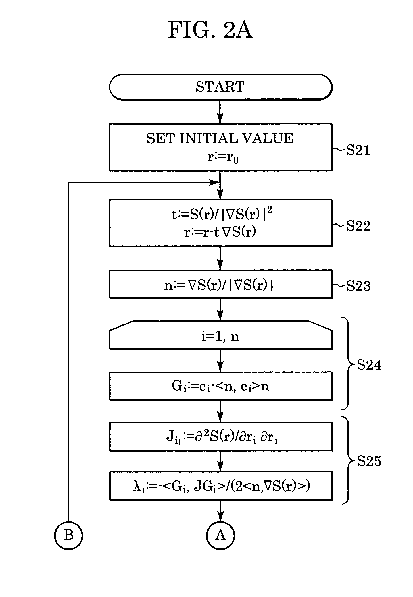
[0042] The method for optimization according to this embodiment includes two steps: linearly approximating the hypersurface S(r) and finding extreme values along curved lines having second-order osculation to the plane tangential to the hypersurface S(r)=c in the projection direction of the unit vectors of each axial direction of the coordinate system. More specifically, the method includes the steps illustrated in the flow chart of FIG. 2. Each step is described below.
[0043] Step S21: Setting the initial value of the point r: Each component of r(0) is r1(o), r2(0), . . . , rn(0). These initial values r1(0), r2(0), . . . , rn(0) are set in the variables r1, r2, . . . , rn whereas r=(r1r2⋮rn),r1,r2,… ,rn∈R.
r1, r2, . . . , rn∈R.
[0044] Step S22: Linearly approximating the hypersurface S(r)=0:
[0045] A straight line in the gradient direction of the hypersurface S(r)=0 is represented as r(t)=r−t∇S(r), where t is a parameter. Since S(r−t∇S(r))=S(r)−t+o(t) in the proximity of the poin...
third embodiment
[0055] The optimization algorithm according to this embodiment includes two steps: linearly and asymptotically approximating a hypersurface S(r)=0 as a constraint and finding an extreme value in the projection direction onto a plane tangential to the hypersurface S(r)=c.
[0056] The optimization algorithm according to this embodiment is extremely effective in solving the problem of determining the interface shape of two types of liquids, or a liquid and a gas, held in a container at a constant volume.
[0057] This kind of problem is formulated into a problem of minimizing the sum of the surface energy and the gravitational energy of the liquids (or liquid and gas). When generalized, such a constrained optimization problem can be perceived as a problem of finding the local minimum of the formulated real function E(r) subject to the constraint S(r)=0.
[0058] Accordingly, the optimization algorithm according to this embodiment includes the steps illustrated in the flow chart of FIG. 3. E...
PUM
 Abstract
Description
Claims
Application Information