Modification of an image of a pattern during an imaging process

a technology of pattern and image, applied in the field of pattern image modification, can solve the problems of affecting the amount of pattern induced distortion, affecting the effect of overlay control, and actual devices having a different distortion from the distortion measured

Inactive Publication Date: 2005-09-22
ASML NETHERLANDS BV
View PDF15 Cites 45 Cited by
  • Summary
  • Abstract
  • Description
  • Claims
  • Application Information

AI Technical Summary

Benefits of technology

[0026] It is an object of the present invention to provide a method to correct for overlay errors wh...

Problems solved by technology

Furthermore the density of a pattern of small features also influences the amount of pattern induced distortion.
Typically the centre of the mask pattern will comprise the devices or products which are relevant to the se...

Method used


Image

  • Modification of an image of a pattern during an imaging process
  • Modification of an image of a pattern during an imaging process
  • Modification of an image of a pattern during an imaging process

Examples


Embodiment Construction

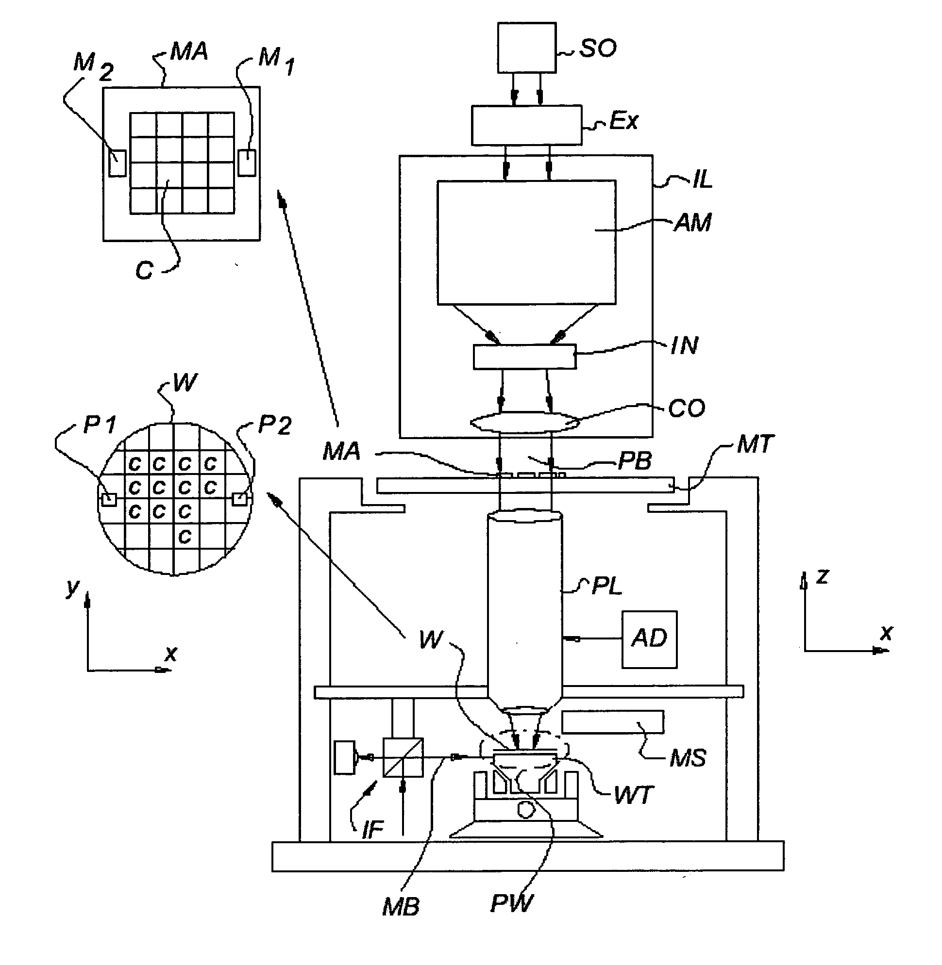
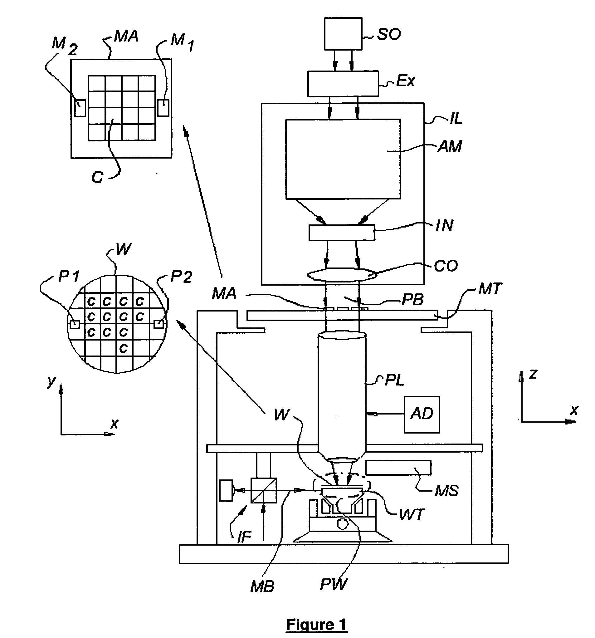
[0068]FIG. 1 schematically depicts lithographic projection apparatus comprising at least one marker structure in accordance with an embodiment of the invention. The apparatus comprises: [0069] an illumination system IL for providing a projection beam PB of radiation (e.g. UV or EUV radiation). In this particular case, the radiation system also comprises a radiation source SO; [0070] a first support structure MT (e.g. a mask table) for supporting a patterning device, MA (e.g. a mask) and connected to a first positioner (not shown) for accurately positioning the patterning device with respect to item PL; [0071] a second support structure WT (e.g. a wafer table) for holding a substrate, W (e.g. a resist-coated silicon wafer) and connected to a second positioner PW for accurately positioning the substrate with respect to item PL; and [0072] a projection system PL (e.g. a reflective projection lens) for imaging a pattern imported to the projection beam PB by patterning device MA onto a t...


PUM


Abstract

A method is provided for modifying an image of a pattern during a lithographic imaging process, where the pattern is arranged on a mask for imaging by a projection system on a surface, and the image is an image formed from the pattern by the projection system. In this method the imaging quality of the projection system is described by selected imaging quality parameters, and the image is adjustable by image adjustment parameters of the projection system. The method comprises the steps of determining an ideal image of the pattern, determining a simulated distorted image of the pattern based on the selected imaging quality parameters; determining a deviation between the simulated distorted image and the ideal image, and adapting the image adjustment parameters during the imaging process to minimize the deviation between the simulated distorted image and the ideal image on the basis of the selected imaging quality parameters.

Description

[0001] This application claims priority from European Patent Application No. 03077204.0, filed Jul. 11, 2003, herein incorporated by reference in its entirety. FIELD OF THE INVENTION [0002] The present invention relates to a method for modifying an image of a pattern during an imaging process, as well as to apparatus for modifying an image of a pattern during an imaging process, and to a lithographic projection apparatus using such a method. BACKGROUND OF THE INVENTION [0003] The present invention finds application in the field of lithographic projection apparatus that encompass a radiation system for supplying a projection beam of radiation, a support structure for supporting a patterning device, which serves to pattern the projection beam according to a desired pattern, a substrate table for holding a substrate; and, a projection system for projecting the patterned beam onto a target portion of the substrate. [0004] The term “patterning device” as employed here should be broadly i...

Claims


Application Information

Patent Timeline
IPC IPC(8): G03F7/20H01L21/027
CPCG03F7/706G03F7/705
Inventor VERSTAPPEN, LEONARDUS HENRICUS MARIEFINDERS, JOZEF MARIAJEUNINK, ANDRE BERNARDUSTEL, WIM TJIBBOVAN DER HOFF, ALEXANDER HENDRIKUS MARTINUS
Owner ASML NETHERLANDS BV
Why Eureka
Try Eureka