
Integrated cleaning apparatus and methods

a cleaning apparatus and integrated technology, applied in the field of cleaning systems, can solve the problems of limited interior cleaning options, several hours may be required for cleaning the treated carpet or upholstery, prior art cleaning processes have a tendency to create an odor of mildew, etc., to achieve better and faster cleaning, increase boiling temperature, and increase thermal energy

Inactive Publication Date: 2005-09-29
V O BROS MECHANICAL L L C
View PDF23 Cites 16 Cited by
  • Summary
  • Abstract
  • Description
  • Claims
  • Application Information

AI Technical Summary

Benefits of technology

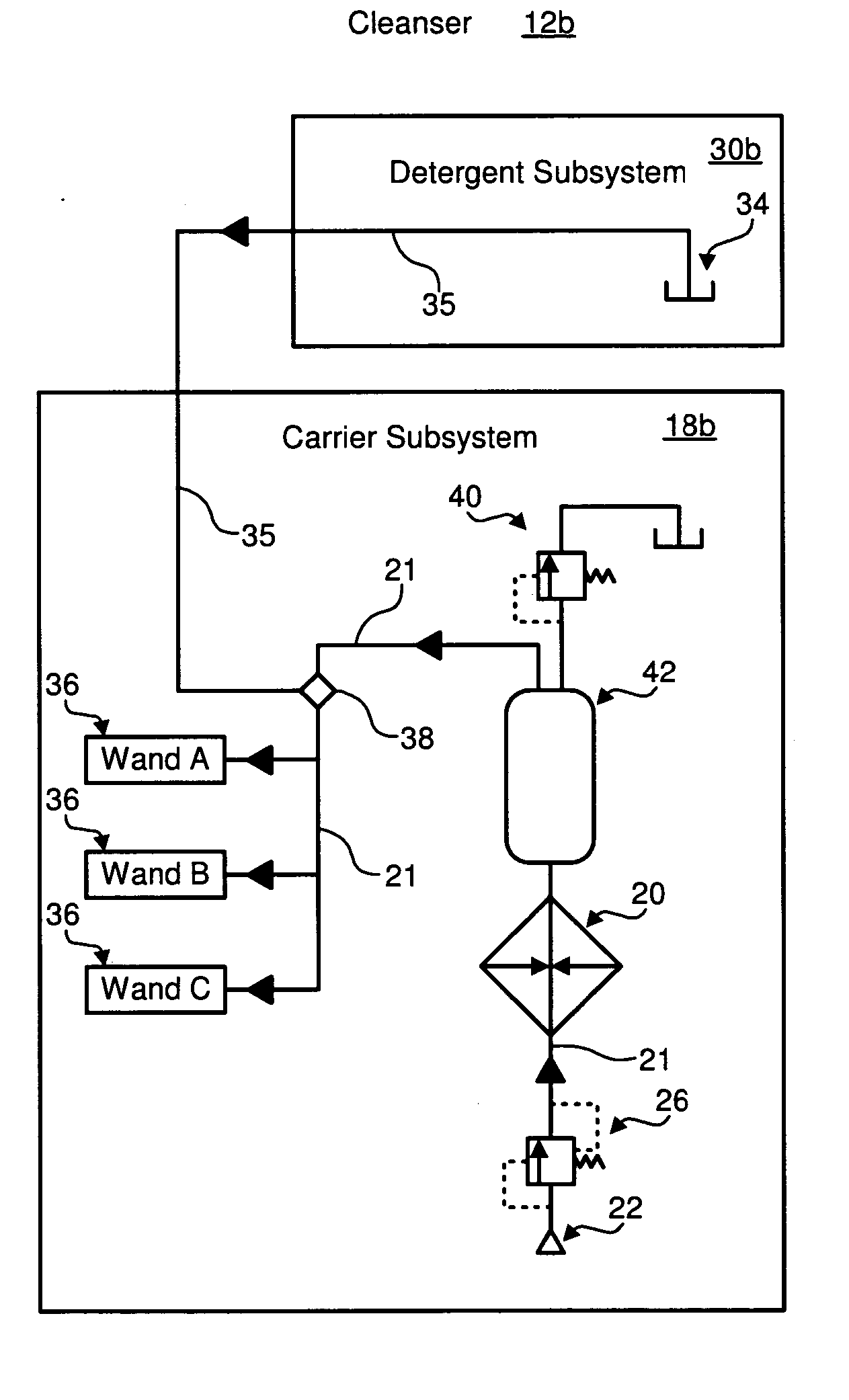
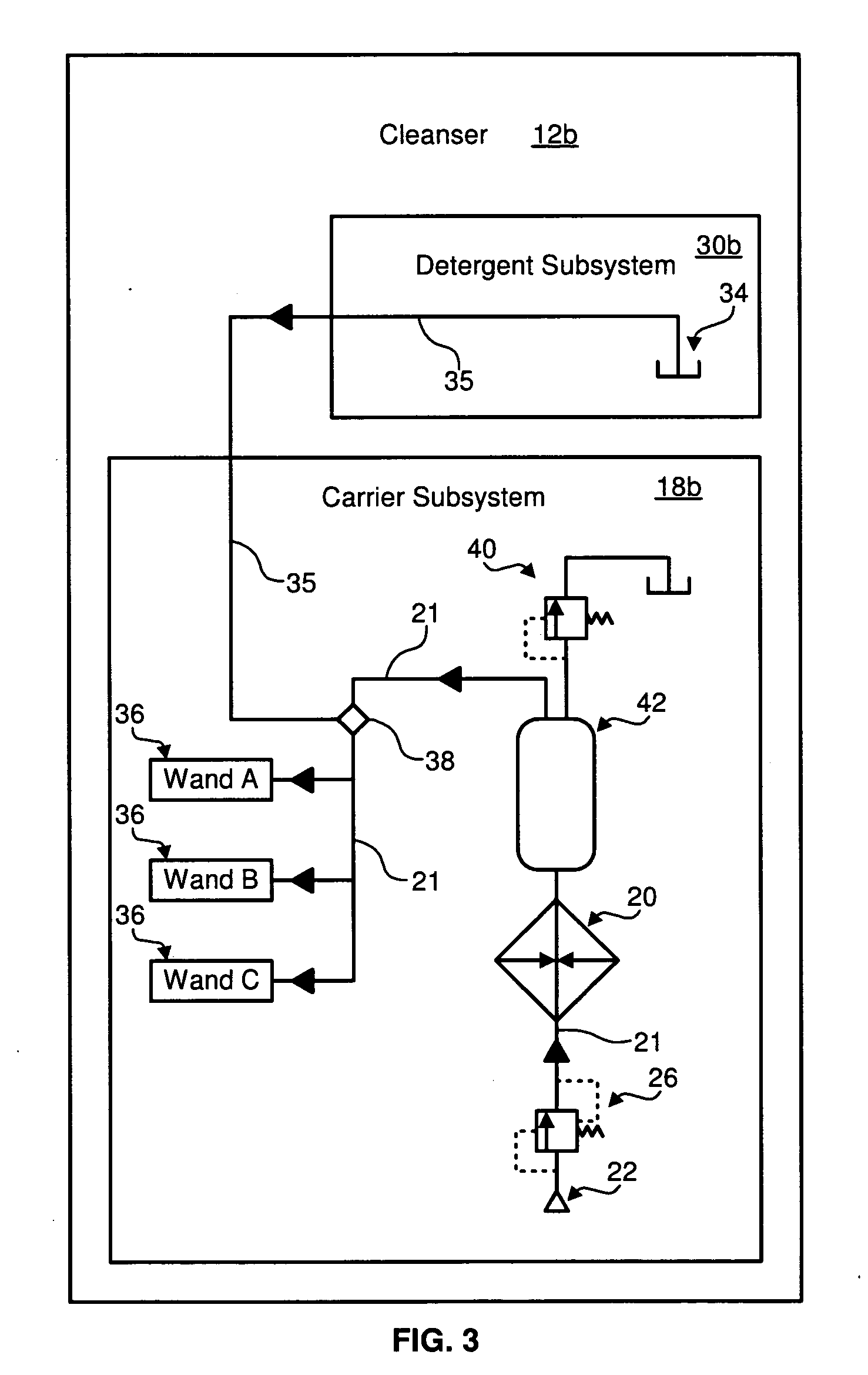
[0012] In selected embodiments, a cleaner may include a heater for heating one or more cleaning fluids before they are transported to a wand for application to the surface being cleaned. Suitable heaters may include heat exchangers, electric heaters, gas heaters, and the like. In some embodiments, the cleanser may heat the cleaning fluids (e.g. water) under pressure to increase their boiling temperature. This may permit the cleaning fluids to have greater thermal energy when applied to the surface.
[0013] In general, the hotter the cleaning fluids, the better and faster the cleaning. For example, the hotter the water used, the less chemical detergents are needed. Certain embodiments in accordance with the present invention may apply water at temperatures range from about 48° C. and about 121° C., or even greater. To maintain the cleaning fluids at the desired temperature at distant locations, the cleaner may recirculate cleaning fluid through the heater. Moreover recirculation conduits and wand conduits may be insulated to reduce heat loss.
[0014] A collector in accordance with the present invention may utilize deep vacuum pumps. In general, deeper vacuums extract the cleaning fluids and dirt better than lower vacuums. As a result, a deeper vacuum generally shortens drying times. Additionally, cleaning fluids will evaporate at a lower temperature under vacuum. Selected collectors in accordance with the present invention may pull a vacuum of 25.4 cm Hg or greater.
[0015] In certain embodiments, a separator may remove the large majority of the liquid from the flow before it reaches the vacuum pump. In some embodiments, the separator may enforce a centrifugal acceleration greater than gravitational acceleration to effect the separation.
[0016] Deep vacuum pumps typically have close tolerances that must be protected from the debris and moisture picked up during the cleaning process. In certain embodiments, one or more filters may be positioned in the flow between the separator and the vacuum pump in order to mitigate the debris and moisture.
[0018] The novel systems in accordance with the present invention may further include a discharge system allowing for continuous operation. That is, removal of the waste liquids without shutting down the collector. By operating selected valves (manually, mechanically, or under computer control), one volume may be taken off-line and emptied while another continues to collect liquids.

Problems solved by technology

However, even with these aids, several hours may be required for cleaning the treated carpet or upholstery.
Additionally, prior art cleaning processes have a tendency to create an odor of mildew.
In the self-serve carwash industry, current interior cleaning options are limited to wet-dry vacuums or vacuum and shampoo systems.
Vacuums acting alone are only able to remove debris that is already loose and easily accessible from the surface of the carpet or upholstery.
Accordingly, a vacuum acting alone is unable to provide a deep clean or remove adhered materials (e.g., grime trapped in soft drink spills, etc.).
A large amount of dirty shampoo remains in the carpet or upholstery.
This residual shampoo may leave a strong chemical smell and quickly attract new dirt.
Regardless of the industry were they are used, known carpet and upholstery cleaning systems are not generally optimized for deep cleaning and fast drying.
For example, some current cleaning systems use large gravity settling tanks that are not easily included within an integrated package.
Such heaters are typically limited to a maximum of 60° C. Moreover, they lack the structures to maintain this temperature throughout the cleaning process.
As appreciated, the water used in such systems cools significantly before it is ever applied to the carpet or upholstery, thereby reducing its cleaning potential and increasing drying time.
Cleaning systems of the prior art typically use vacuum pumps that are incapable of producing sufficient suction.
Furthermore, known systems lack the structure necessary to implement more effective vacuum pumps.
Current cleaning systems do not provide continuous operation.
In operations utilizing multiple cleaning stations, this downtime may be a significant nuisance and thereby reduce the overall efficiency of the cleaning operation.

Method used


Image

  • Integrated cleaning apparatus and methods
  • Integrated cleaning apparatus and methods
  • Integrated cleaning apparatus and methods

Examples


Embodiment Construction

[0039] It will be readily understood that the components of the present invention, as generally described and illustrated in the drawings herein, could be arranged and designed in a wide variety of different configurations. Thus, the following more detailed description of the presently preferred embodiments of the system and method of the present invention, as represented in the drawings, is not intended to limit the scope of the invention, as claimed, but is merely representative of various embodiments of the invention. The presently preferred embodiments of the invention will be best understood by reference to the drawings, wherein like parts are designated by like numerals throughout.

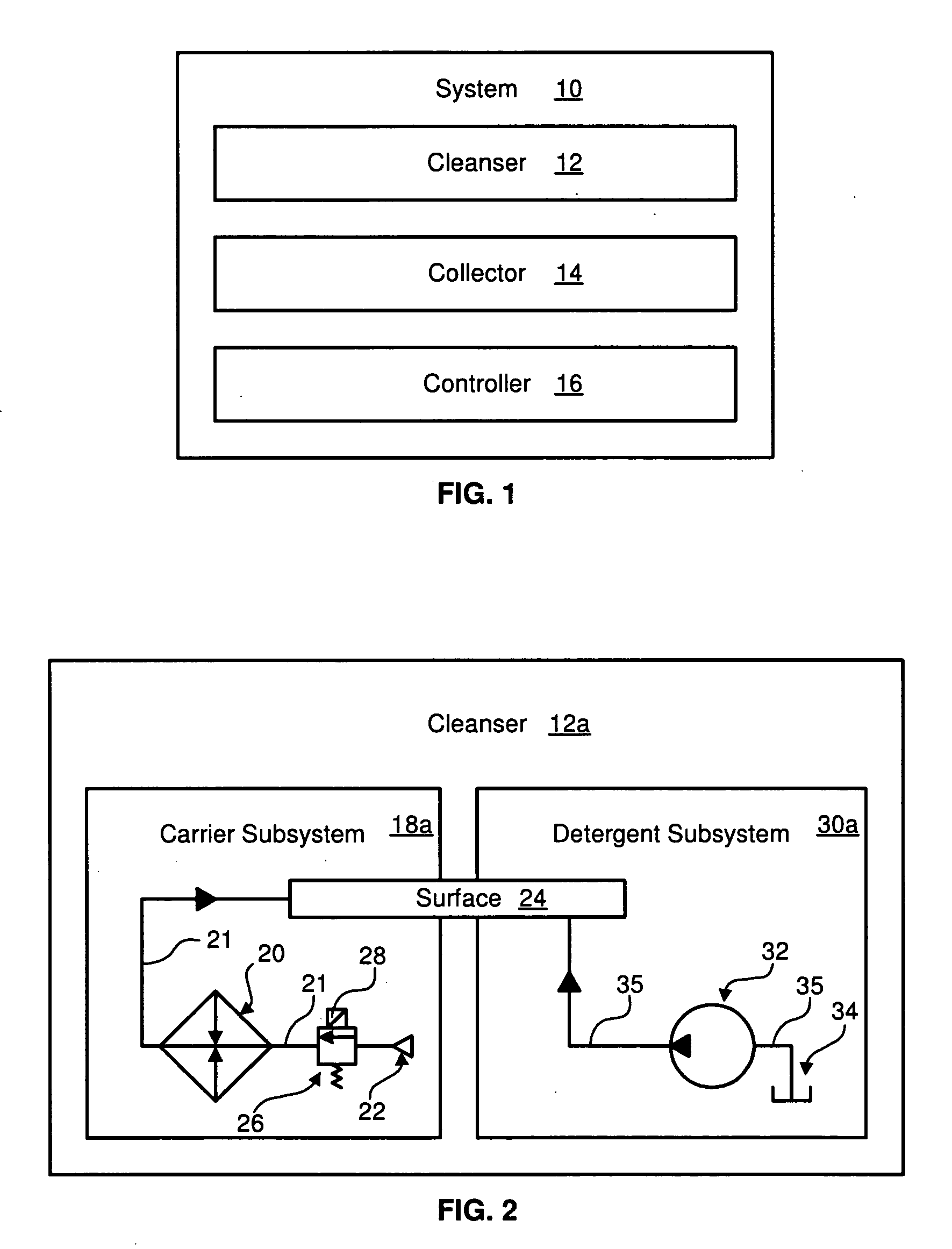
[0040] Referring to FIG. 1, an integrated cleaning system 10 in accordance with one presently preferred embodiment of the present invention may include a cleanser 12, a collector 14, and a controller 16. The cleanser 12 may condition and distribute cleaning fluids for dissolving, trapping in solutio...


PUM


Abstract

Apparatus and method providing efficient cleaning of various surfaces. The apparatus including a collector and a controller. The collector having an inlet conduit, a vacuum pump, a first valve, a second valve, a tank, and a separator. The inlet conduit connects to an inlet aperture of the separator, the vacuum pump connects to an outlet aperture of the separator, the first valve regulates flow between a drain aperture of the separator and an inlet aperture of the tank, and the second valve regulates flow through a drain aperture of the tank. One or more filters may filter flow between the separator and the vacuum pump. The controller may be programmed to, upon sensing a full tank, selectively close the first valve and open the second valve and, after the passage of a selected period of time, selectively close the second valve and open the first valve. The collector and controller may provide an integrated, compact cleaning system that supports continuous operation.

Description

RELATED APPLICATIONS [0001] This application claims the benefit of U.S. Provisional Patent Application Ser. No. 60 / 557,211, filed on Mar. 29, 2004 for CYCLONE EXTRACTOR SYSTEM AND METHOD, which is incorporated herein by reference.BACKGROUND [0002] 1. The Field of the Invention [0003] This invention relates to cleaning systems and, more particularly, to novel systems and methods for cleaning carpets and upholstery using high vacuum, high temperature, continuously operating cleaning systems. [0004] 2. The Background Art [0005] Currently, in the automotive detailing industry, dirty carpets and upholstery are treated with chemicals (e.g. surfactants) or chemical and water combinations to help lift grime and debris from the surface. The resulting mixture may then removed by a vacuum from the treated carpet or upholstery, which is then left to dry. Doors of the automobile are often left open to aid in drying. On occasion, heaters may be used to speed the drying process. However, even with...

Claims


Application Information

Patent Timeline
IPC IPC(8): A47L7/00A47L9/28A47L11/30B60S3/00
CPCA47L7/0009A47L7/0028A47L7/0038B60S3/008A47L9/2857A47L9/2889A47L9/2805
Inventor VANORDEN, SCOTT T.LARSSON, JOHN A.LYON, MARVIN G.TAYLOR, PAUL H.
Owner V O BROS MECHANICAL L L C
Learn More