Method and apparatus for wall component drainage

a technology of wall components and drainage methods, which is applied in the direction of roofs, sills/thresholds, construction, etc., can solve the problems of high moisture in the wall interior, affecting the drainage effect,

Inactive Publication Date: 2005-09-29
LAWSON ROBERT CARL +1
View PDF24 Cites 35 Cited by
  • Summary
  • Abstract
  • Description
  • Claims
  • Application Information

AI Technical Summary

Benefits of technology

[0012] The above discussed and other drawbacks and deficiencies are overcome or alleviated by a pan flashing to prevent water from entering a building by wicking underneath a door or window. In an exemplary embodiment, the pan flashing includes a pitched pan configured to wrap around a bottom of the door or window on three sides defining a bottom surface thereof, the pan having a substantially rectangular shape in plan; a plurality of spaced wedges extending from the pitched pan, an exposed top surface of the plurality of spaced wedges corresponding to a horizontal plane and providing a weight bearing support for a sill disposed thereover; a front flange projecting perpendicularly and downwardly from a front edge defining a fourth side of the rectangular shape, the flange being fluted for fluid communication with channels defined by the plurality of spaced wedges, thus allowing ventilation up through the flutes to the pitched pan residing under the door or window and allowing a place for the water to flow out of the pan; and a front wall coplanar with the front flange and extending upwardly and downwardly from the pan, the front wall providing an attachment means for securing to a vertical stud framing the door or window, when installed.

Problems solved by technology

Water in the form of rainwater, ice, snow, or the like, penetrates in and around building wall components, e.g., windows and doors, and then migrates downwardly beneath the wall component resulting in high moisture in the wall interior.
In traditional building construction where the walls are formed of a wood frame with an outer cladding of wood, brick or concrete, this moisture has created some problems, although the porosity of the cladding allows the moisture to escape.
In more modern construction, however, there is a trend toward the use of cladding materials that result in a building that is as air tight as possible.
With these non-porous cladding materials, moisture entering the wall interior may be trapped, creating a highly moist environment that causes the wood frame components of the building to rot, and metal components to rust or corrode.
In addition, the moist environment is a breeding ground for wood consuming insects, causing further decay.
This problem is accelerated in hot and humid environments.
These attempts have not been completely successful.
Sealants are not only difficult to properly install, but tend to separate from the wall component or wall due to climatic conditions, building movement, the surface type, or chemical reactions.
Flashing is also difficult to install and may tend to hold the water against the wall component, accelerating the decay.
The use of sealants and flashing is also limited to the attempted minimization of water collection in building walls in new construction, and the further collection in existing structures.
These materials are of no value in addressing the problem of water that has already entered a building wall interior.
Thus, with solutions presented in the prior art, water still enters the wall interior, and the problem is further compounded by the prevention of any evaporation of the water already in the wall interior.
The problem of water penetration has prevented the full use of new building cladding materials, and has resulted in many buildings with rotting framing structures, requiring extensive and expensive retrofitting.
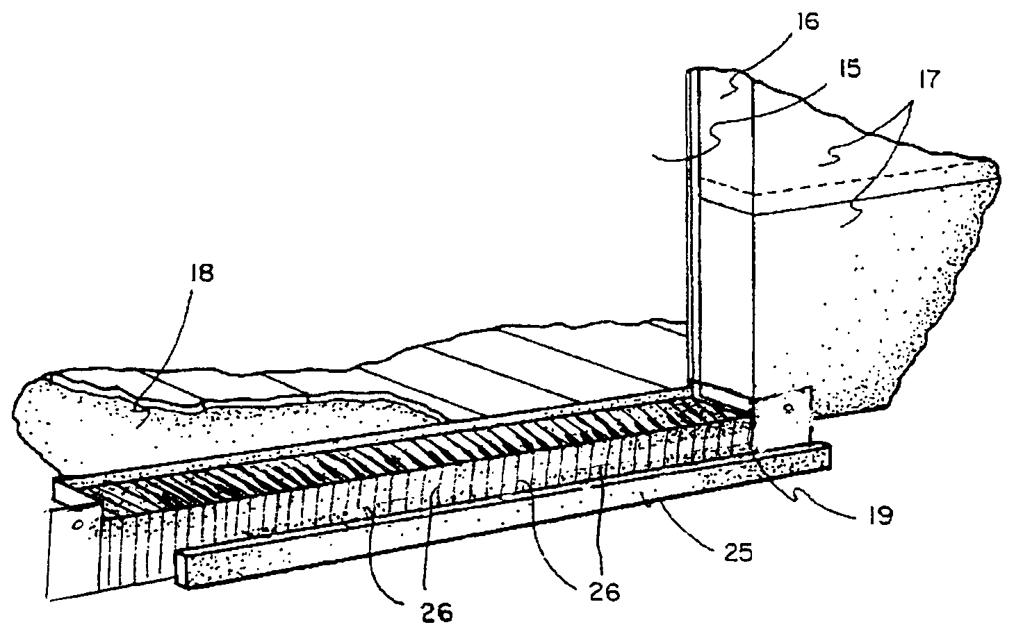
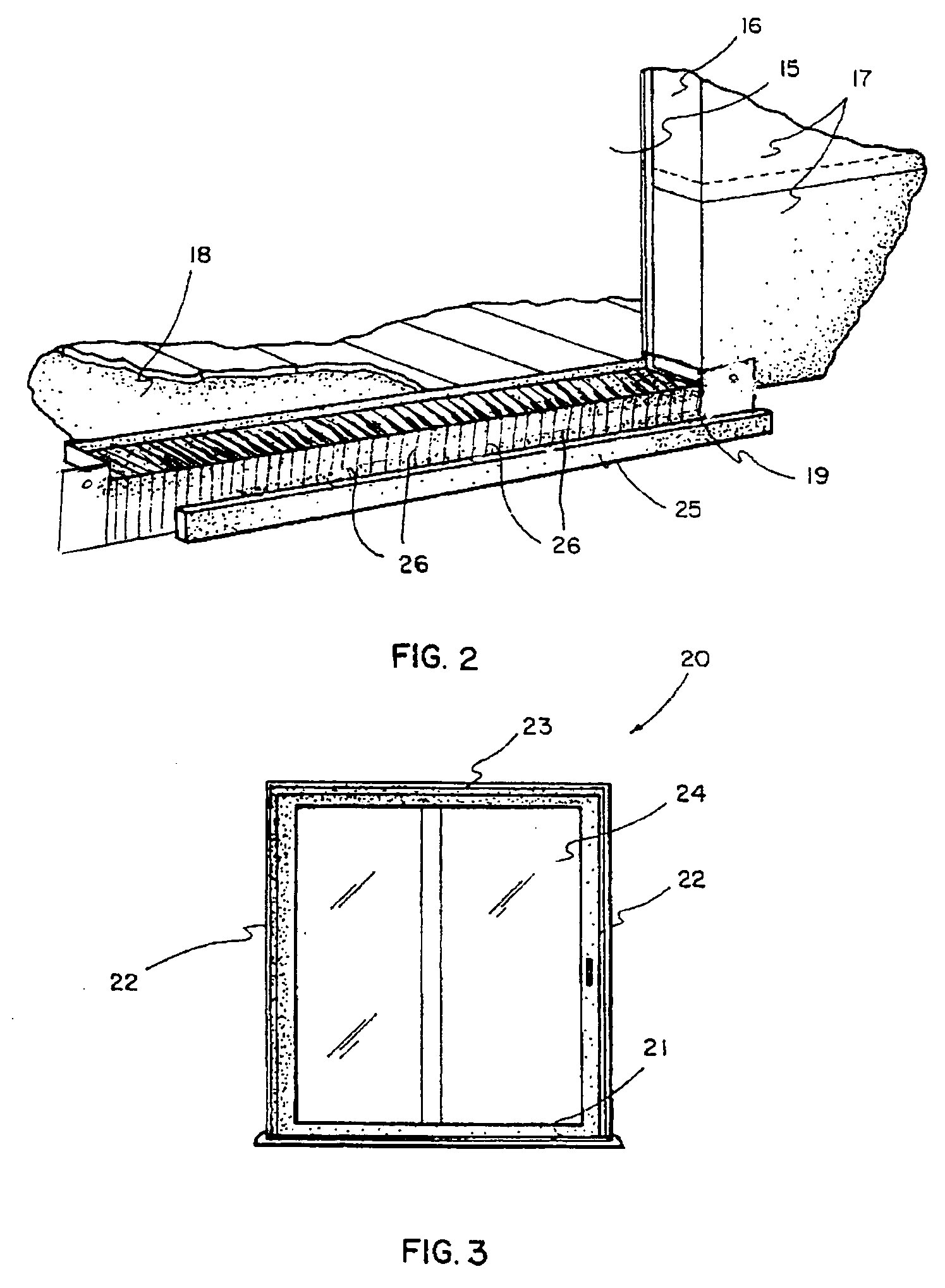
In particular, there has always been a problem with exterior doors and preventing moisture from being blown under and around exterior doors.
The result of water ingressing under the entry doors not only causes the underside of the interior floor and the surface of the sub floor to become wet, but over a period of time can cause the flooring to rot as well as the floor joist and doorjamb.
When this happens, very expensive repairs must be made.
Once this is accomplished and a new door installed, the process starts all over with the floor becoming wet and rot setting in.
Whenever someone installs a door or window there is a chance for water to enter the structure.
When it rains, water can splash off the exterior steps or deck, wick under the sill of the door and get under the flooring inside the structure.
With the water between the sub floor and the flooring, it can do substantial damage ruining the flooring in front of, and anything just below, the door or window.
As discussed above, the repeated entry of water into the structure will eventually cause substantial dry rot.
The lead or aluminum can tear easily, making this process somewhat delicate.
Once installed, the interior finishing construction exposes the pan to a number of potential hazards that can, and often do, tear it.
If the integrity of the pan is compromised, the water is able to enter the structure.
If everything works properly with the pan, the doorsill sits in a pan of water eventually causing it to rot.
The problems and inconvenience of pan flashing has caused the majority of installers to try alterative methods, most notably caulk.
The advent of caulk has caused as many problems as it has solved as described above.
The areas to be caulked can be difficult to access and, as such, are prone to having gaps in the bead of caulk.
To compensate for the potential for gaps in the caulk, the installer uses a large volume of caulk, which causes problems with the interior and exterior finishing construction.
Interior and exterior finishing carpenters tend to trim the excess caulk in order to finish the structure, which can introduce gaps in the caulk allowing water to enter the structure.
In the long term, the constant motion of the doorsill and the sub floor due to seasonal temperature and humidity fluctuations puts a lot of stress on the caulk.
This stress, coupled with the tendency of the caulk to dry out over time, will cause gaps in the caulk allowing water to enter the structure.

Method used


Image

  • Method and apparatus for wall component drainage
  • Method and apparatus for wall component drainage
  • Method and apparatus for wall component drainage

Examples


Embodiment Construction

[0022] Referring now to FIGS. 1-3, a one-piece entry door flashing pan in accordance with an exemplary embodiment, indicated generally at 10, is preferably molded in a single piece and can be composed of any suitable material such as plastic or the like. Also, the pan 10 can be manufactured by joining a plurality of separately formed components. For example, a pan portion can be formed of an extruded base section and an injection molded upper section forming three side walls, while a lip extending from the base section opposite the three side walls can also be extruded. Since the selection of materials of this type are well known to those skilled in the art, further detailed discussion of this portion of the same is not deemed necessary. Furthermore, it will be noted that although an entry door flashing pan is described in conjunction with a hinged door in an exemplary embodiment, entry door flashing pan 10 may be employed with a sliding door, window or other building wall component...


PUM


Abstract

A pan flashing including a pitched pan configured to wrap around a bottom of the door or window on three sides defining a bottom surface thereof; a plurality of spaced wedges extending from the pitched pan providing a weight bearing support for a sill disposed thereover; a front flange projecting perpendicularly and downwardly from a front edge defining a fourth side, the flange being fluted for fluid communication with channels defined by the plurality of spaced wedges, thus allowing ventilation up through the flutes to the pitched pan residing under the door or window and allowing a place for the water to flow out of the pan; and a front wall coplanar with the front flange and extending upwardly and downwardly from the pan, the front wall providing an attachment means for securing to a vertical stud framing the door or window, when installed.

Description

BACKGROUND OF INVENTION [0001] Water in the form of rainwater, ice, snow, or the like, penetrates in and around building wall components, e.g., windows and doors, and then migrates downwardly beneath the wall component resulting in high moisture in the wall interior. In traditional building construction where the walls are formed of a wood frame with an outer cladding of wood, brick or concrete, this moisture has created some problems, although the porosity of the cladding allows the moisture to escape. Also, openings in the exterior of the walls, either due to the nature of the materials used, or the addition of ventilation openings, have aided in moisture removal. [0002] In more modern construction, however, there is a trend toward the use of cladding materials that result in a building that is as air tight as possible. These materials include, for example, exterior insulation and finish systems (EIFS), insulated brick, polyethylene sheeting, and polyvinyl siding. With these non-p...

Claims


Application Information

Patent Timeline
Patent Type & Authority Applications(United States)
IPC IPC(8): E04D15/00E06B1/70
CPCE06B1/70
Inventor LAWSON, ROBERT CARLLAWSON, ROBERT CARL JR.
Owner LAWSON ROBERT CARL
Why Eureka
Try Eureka