Square-wave laser bonding

a laser and laser technology, applied in the direction of welding apparatus, metal-working equipment, catheters, etc., can solve the problems of increasing the rigidity of the region of the bonding, providing unacceptable seals, and adding layers to the thickness of the area being bonded

Inactive Publication Date: 2005-09-29
ABBOTT CARDIOVASCULAR
View PDF13 Cites 10 Cited by
  • Summary
  • Abstract
  • Description
  • Claims
  • Application Information

AI Technical Summary

Problems solved by technology

However, this method provides unacceptable seals for when bonding components having multiple lumens, multiple shafts, or irregular geometries, for example, the non-circular geometry of the proximal and distal balloon seals of a multi-lumen balloon radiation centering catheter.
However, the adhesive layers add to the thickness of the area being bonded and increase its rigidity at

Method used


Image

  • Square-wave laser bonding
  • Square-wave laser bonding
  • Square-wave laser bonding

Examples


Embodiment Construction

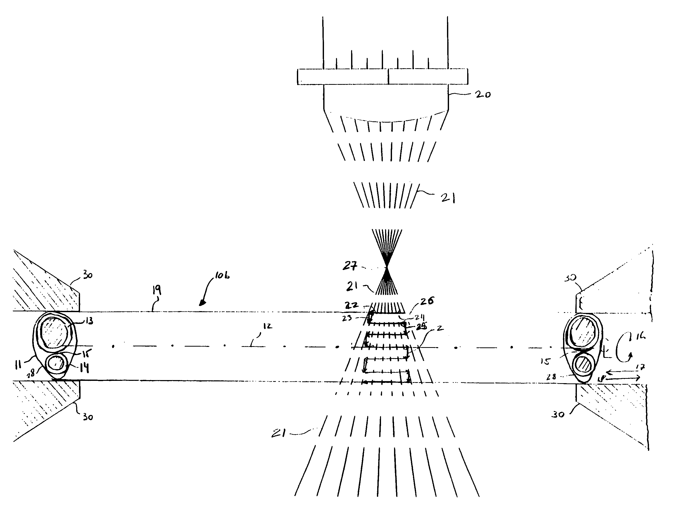
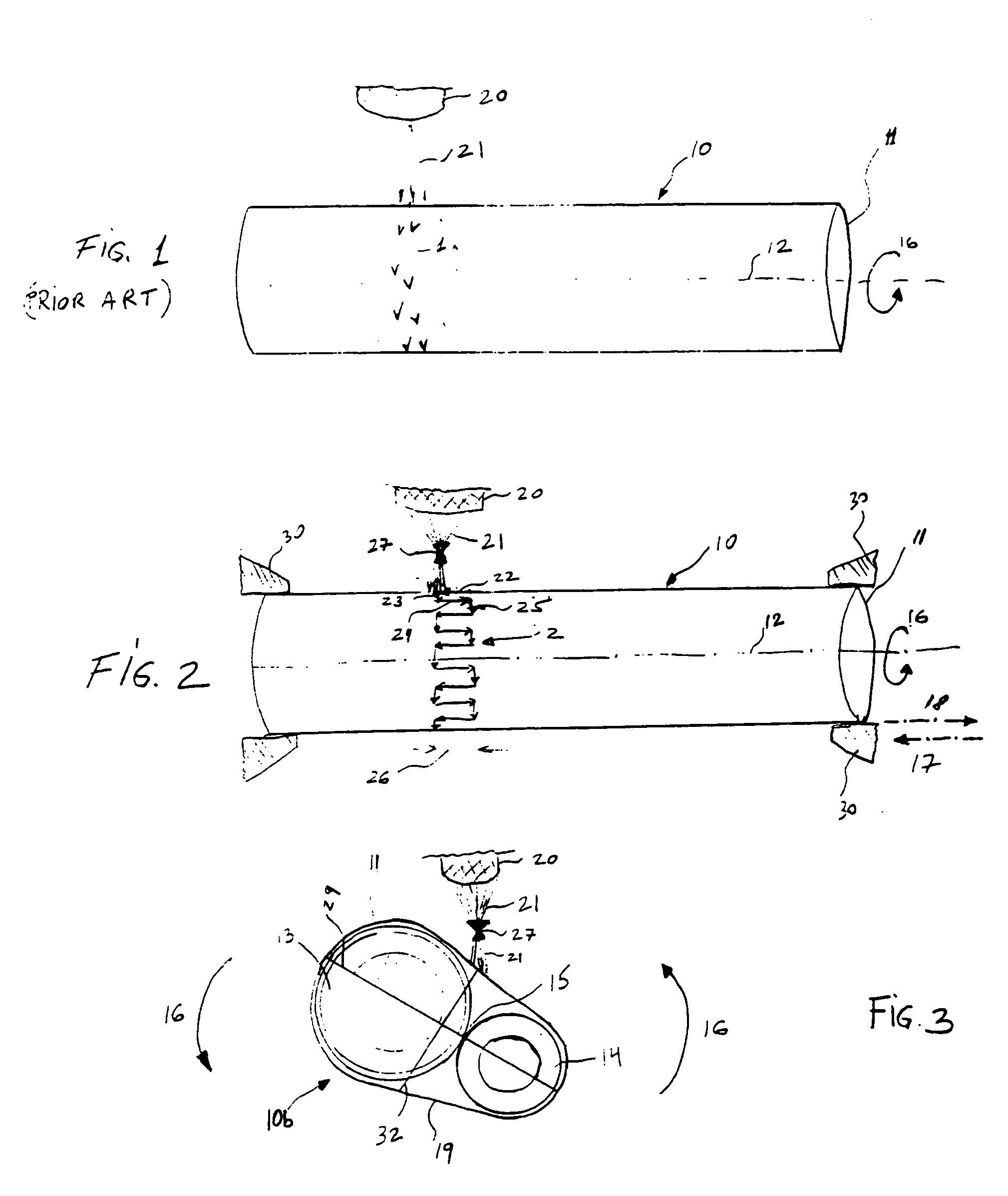
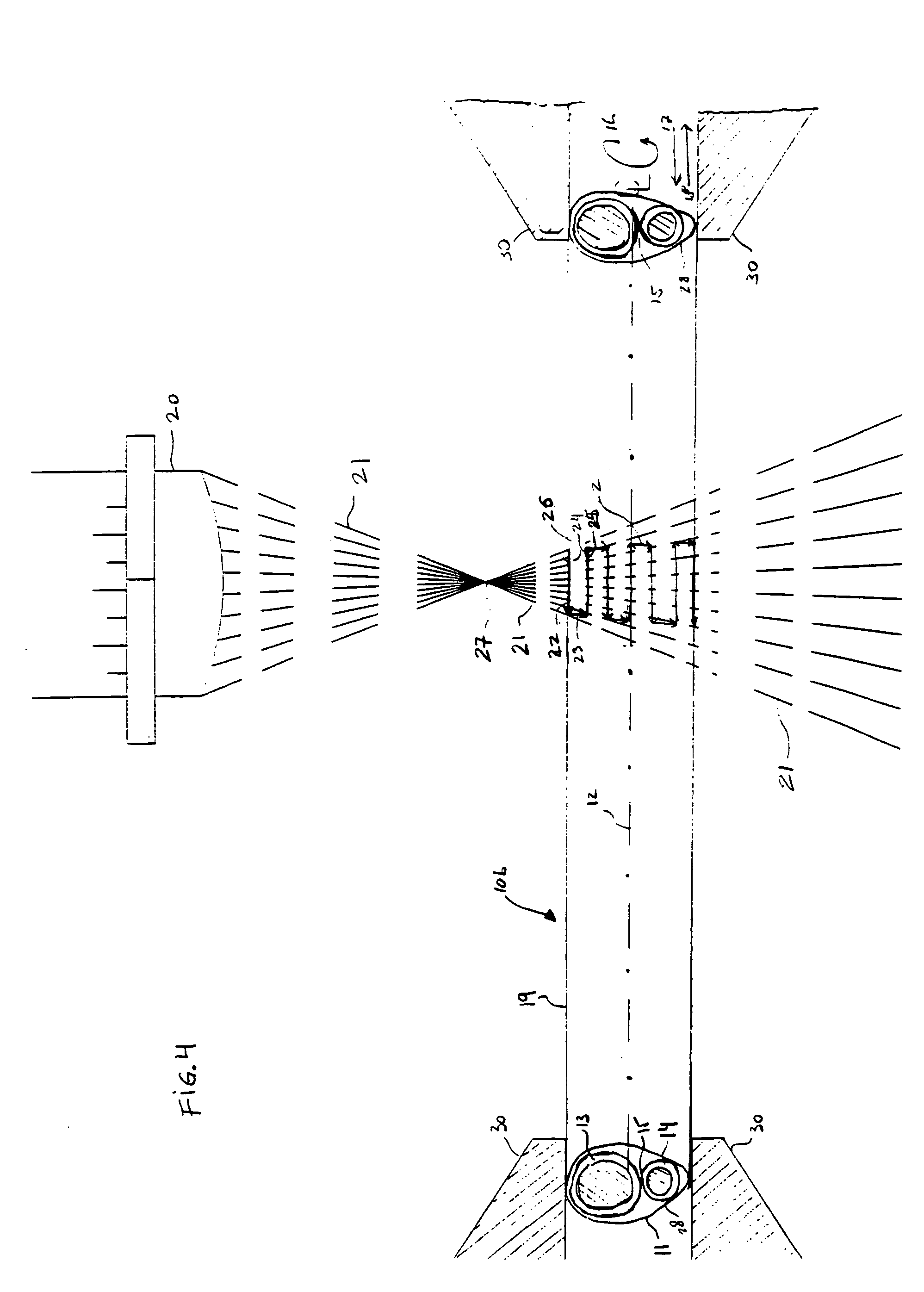
[0022] A square-wave laser seal pattern and seal performed around the circumference of a shaft to bond materials and method for providing the same is described. The present invention improves the bonding and sealing of multiple lumen, multiple shaft, and irregular geometric components. For example, the present invention may be used to bond a material to a catheter shaft, where the conventional helical or rings laser seal pattern is unable to target and seal the material in the groove of a multiple lumen balloon.

[0023] The square-wave laser seal pattern of the present invention may be used in bonding components together, and is especially useful for bonding components of non-circular geometries such as multiple lumens and multiple shaft components as well as components with other irregular geometries. The square-wave laser seal pattern is also well suited to be used for performing the proximal and distal balloon seals for a single or multi-lumen balloon catheters, such as a multi-lu...


PUM

PropertyMeasurementUnit
Angleaaaaaaaaaa
Angleaaaaaaaaaa
Lengthaaaaaaaaaa

Abstract

The present invention provides a square-wave laser seal pattern made by first directing a laser beam onto an shaft while the shaft is moving in a horizontal direction relative to a laser device so as to create a horizontal laser seal bond segment. Next, with the shaft rotating about a shaft longitudinal axis, the laser beam is directed onto the shaft so as to create a vertical laser seal bond segment. By alternately creating and coupling together a plurality of horizontal and vertical laser seal bond segments, a square-wave laser seal is formed around a circumference of the shaft. The shaft's movement in a horizontal direction relative to a laser beam may be either at a constant speed or a variable speed so as to control the amount of laser energy heat impacting the shaft material.

Description

BACKGROUND OF THE INVENTION [0001] 1. Field of the Invention [0002] The present invention relates to providing tight seals along shafts by means of laser energy and more particularly to laser bonding of medical device shaft geometries. [0003] 2. Description of Related Art [0004] Balloon catheters are well known for their utility in treating certain types of obstructions in blood vessels. In a Percutaneous Transluminal Coronary Angioplasty (PTCA or balloon angioplasty) procedure, catheters are inserted into the cardiovascular system. A pre-shaped guiding catheter is positioned in the coronary artery and then a dilatation catheter having a distensible balloon portion is advanced through the branches of the coronary artery until the balloon portion traverses or crosses a stenotic lesion. The balloon portion is then inflated with a fluid to compress the atherosclerosis in a direction generally perpendicular to the wall of the artery, thus dilating the lumen of the artery. [0005] In the ...

Claims


Application Information

Patent Timeline
IPC IPC(8): A61M25/00B23K26/00B23K26/08
CPCA61M25/1034B23K26/083B23K26/0823A61M25/1036
Inventor CHIU, JESSICASUH, LARA K.WEN, ARTHUR
Owner ABBOTT CARDIOVASCULAR
Why Eureka
Try Eureka