Method for laser bonding

A bonding method and laser technology, which is applied in the field of laser bonding technology, can solve problems such as pressure deviation, and achieve the effects of improving adhesion, reducing poor welding, and high reliability

Inactive Publication Date: 2014-02-05
HITACHI LTD
View PDF5 Cites 5 Cited by
  • Summary
  • Abstract
  • Description
  • Claims
  • Application Information

AI Technical Summary

Problems solved by technology

In addition, it is also known that there is a problem that deviation occurs during pressurization if a solid alloy material is interposed.

Method used


Image

  • Method for laser bonding
  • Method for laser bonding
  • Method for laser bonding

Examples


Embodiment 1

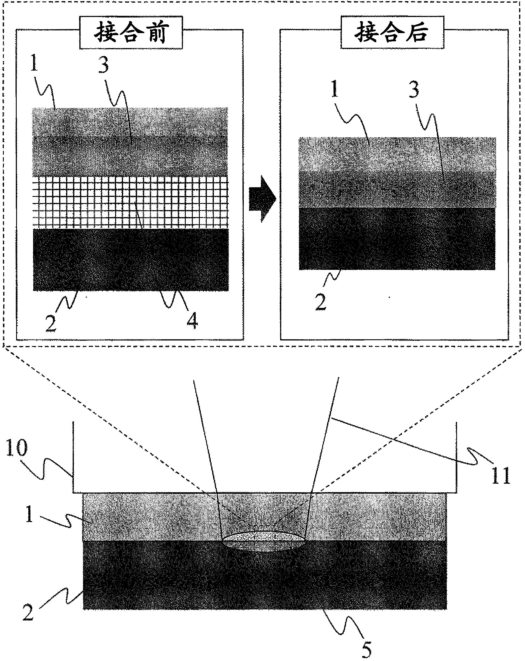
[0034] figure 1 It is a cross-sectional view showing an example of the laser bonding method of resins according to the present invention. In this embodiment, a light-transmitting first thermoplastic resin 1 and a second thermoplastic resin 2 having a light-absorbing property higher than that of the first thermoplastic resin 1 are included. Surface modification treatment is performed to form an oxide layer 3 containing more oxygen than the first thermoplastic resin of the main body at the joint interface, and laser welding is performed under pressure with the liquid intermediate material 4 interposed therebetween.

[0035] For the intermediate material 4 , it is preferable to use a liquid (including a colloidal solution (sol)) material that can sufficiently fill the gap between the thermoplastic resins 1 and 2 . Therefore, it is particularly preferable to use a member with a viscosity of 1000 mPa·s or less, and a solvent with low flammability such as pure water and ethanol, a ...

Embodiment 2

[0046] Figure 6 It is a cross-sectional view showing an example of the laser bonding method of resin and metal of the present invention. Surface modification treatment is performed on the joint interface side of the first thermoplastic resin 1 before joining, and the metal 8 side is pressurized with the liquid intermediate material 4 interposed between the first thermoplastic resin 1 and the metal 8 . Unlike Example 1, laser joining is performed by making laser beam 11 incident from the metal 8 side. By setting it as such a structure, the problem of the transmittance of a thermoplastic resin material which is one of the problems of laser welding is solved. However, in this case, the thickness of the metal 8 is preferably as thin as 4 mm or less. Furthermore, if the surface of the metal 8 to which the laser beam 11 is irradiated is blackened in advance, the absorption rate of the laser beam increases, and the necessary laser power can be reduced, which is a desirable aspect....

Embodiment 3

[0052] Figure 8 It is a cross-sectional view showing another example of the laser bonding method of resins or resins and metals according to the present invention. exist Figure 8 In this case, the pressurizing material 10 is used to pressurize the first thermoplastic resin 1 in a direction (downward in the drawing). If the laser beam 11 is irradiated when the transmittance of the first thermoplastic resin 1 to the laser beam 11 is relatively low at about 20%, there may be cases where the necessary power increases depending on the combination, and the thermoplastic resin 1 on the laser irradiation side Carbonization occurs on the outermost surface, causing problems such as inability to perform laser bonding or adhesion to pressurized materials. Also, even when pressurization is performed using glass, which is a pressurizing material 10 having high thermal conductivity, the glass cannot be brought into contact with the surface of the thermoplastic resin 1 at the interface le...


PUM

PropertyMeasurementUnit
viscosityaaaaaaaaaa
elastic modulusaaaaaaaaaa

Abstract

A method for laser bonding is provided in which interfacial strength between two thermoplastic resins or between a resin and a metal is heightened to render tenacious bonding possible, and bonding failures due to a remaining space can be significantly diminished. In order to solve the problem, the method includes, before bonding, a step in which the bonding surface of at least a first thermoplastic resin is subjected to a surface modification treatment to thereby form an oxidized layer that contains a larger number of oxygenic functional groups than in the bulk thermoplastic resin. A liquid intermediate material is interposed between the first thermoplastic resin and a second thermoplastic resin or a metal, and the stack in this state is pressed and bonded by laser irradiation.

Description

technical field [0001] The present invention relates to a laser joining technique characterized in that thermoplastic resins or resins and metals are welded or joined together using a laser. Background technique [0002] Thermoplastic resins have excellent processability and a large degree of freedom in shape, so they are widely used in general industrial applications such as automobiles, electrical equipment, medical treatment, and biological equipment. Become the material around people. At first, it was used as a substitute for natural raw materials such as wood and paper, but now a large number of so-called special products that cannot be produced without using plastic materials have been developed. Therefore, if the optimal material is fully designed and developed by the optimal processing method, there remains the possibility of producing new products that have not been hitherto. [0003] In particular, with the trend of more complex product structures and lower costs...

Claims


Application Information

Patent Timeline
Patent Type & Authority Applications(China)
IPC IPC(8): B29C65/16B23K26/21B23K26/32
CPCB29C65/1616B29C66/43B29C65/1635B29C66/73118B29C66/8122B29C66/30322B29C66/1122B29C65/8215B29C66/73162B29C66/73921B29C66/742B29C66/342B29C66/24249B29C66/71B29C66/0016B29C66/81267B29C66/939B29C65/1677B29C66/73115B29C66/7392B29C65/1654B29C65/48B29C66/73116B29C66/73117B29C65/1612B29C66/028B29C66/712B29C66/7422B29C66/7428B29C66/74281B29C66/74283B29C66/74285B29C66/7461B29C66/9161B29C66/919B29C66/934B29K2909/08B29K2023/38B29K2077/00B29K2081/04B29K2081/06B29K2079/085B29K2071/00B29K2069/00B29K2067/006B29K2067/003B29K2067/00B29K2059/00B29K2055/02B29K2033/12B29K2027/18B29K2027/08B29K2027/06B29K2025/08B29K2025/06B29K2023/12B29K2023/06
Inventor 荒井聪日向野健史
Owner HITACHI LTD
Why Eureka
Try Eureka