Eureka AIR delivers breakthrough ideas for toughest innovation challenges, trusted by R&D personnel around the world.

Junction plate assembly for undersea hydraulic couplings

Active Publication Date: 2005-09-29
NAT COUPLING
View PDF30 Cites 7 Cited by
  • Summary
  • Abstract
  • Description
  • Claims
  • Application Information

AI Technical Summary

Benefits of technology

[0017] The present invention overcomes the above mentioned problems and disadvantages by providing a junction plate or manifold plate assembly for hydraulic coupling members wherein the junction plates are moved together and apart by cams and cam followers attached to a central shaft. One of the junction plates to which coupling members are connected includes opposing sloped cam surfaces. The central shaft extending between the junction plates has cam followers, which may be rollers or bearings. When the central shaft is rotated, a first cam follower moves up a sloped cam surface and a second cam follower moves down a opposing sloped surface. The sloped cam surfaces translate the rotational movement of the central shaft to axial movement to bring the two manifold plates together or apart depending on the direction of rotation of the central shaft. When the engagement cam follower reaches the end of its sloped cam surface, the male and female coupling members are fully engaged. Likewise, when the disengagement cam follower reaches the detent at the end of its sloped cam surface, the male and female coupling members are functionally disengaged and the junction plates can be fully separated, if desired. The rotational movement necessary to bring the junction plates and couplings together or apart may be accomplished manually by a diver using a handle attached to the central shaft or with a remotely operated vehicle at subsea depths. The invention has particular application in deep water where it assists installers in overcoming the great hydrostatic forces encountered at such depths.

Problems solved by technology

These locking devices lock the coupling members together after the male end coupling members are fully engaged, and do not assist in bringing the male and female members together into full engagement before locking.
A combination of these forces may result in difficulty simultaneously engaging the male and female coupling members on opposing junction plates, and also result in substantial separational forces after the coupling members are connected.
However, threaded connections have the disadvantages of marine growth buildup in the threads and galling of the threads.
This requires time to accomplish and during this time the hydraulic couplings are not fully made up.
This presents the opportunity for fluid loss or sea water entry.
However, lock sleeves are relatively heavy and bulky, which is undesirable in the subsea environment.
Other problems are caused by a buildup of silt, ocean debris and marine growth in the lock sleeves.
The buildup of silt, ocean debris and marine growth may result in jamming the lock sleeves and especially the locking balls.
This apparatus, however, only provides mechanical advantage for bringing the junction plates closer to one another; no mechanical assist is available for separating the plates—i.e., disconnecting the couplings mounted thereon.

Method used


Image

  • Junction plate assembly for undersea hydraulic couplings
  • Junction plate assembly for undersea hydraulic couplings
  • Junction plate assembly for undersea hydraulic couplings

Examples


Embodiment Construction

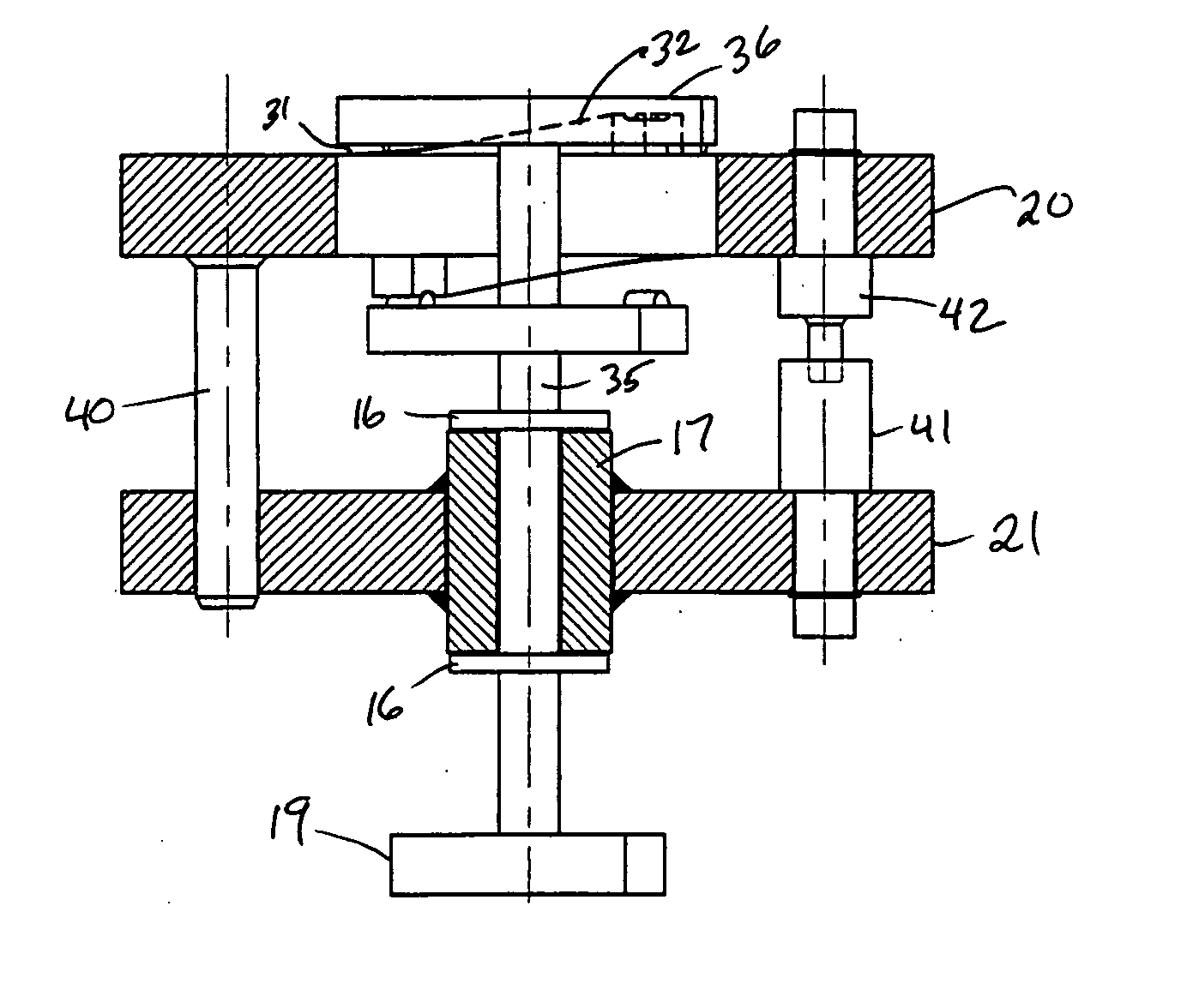
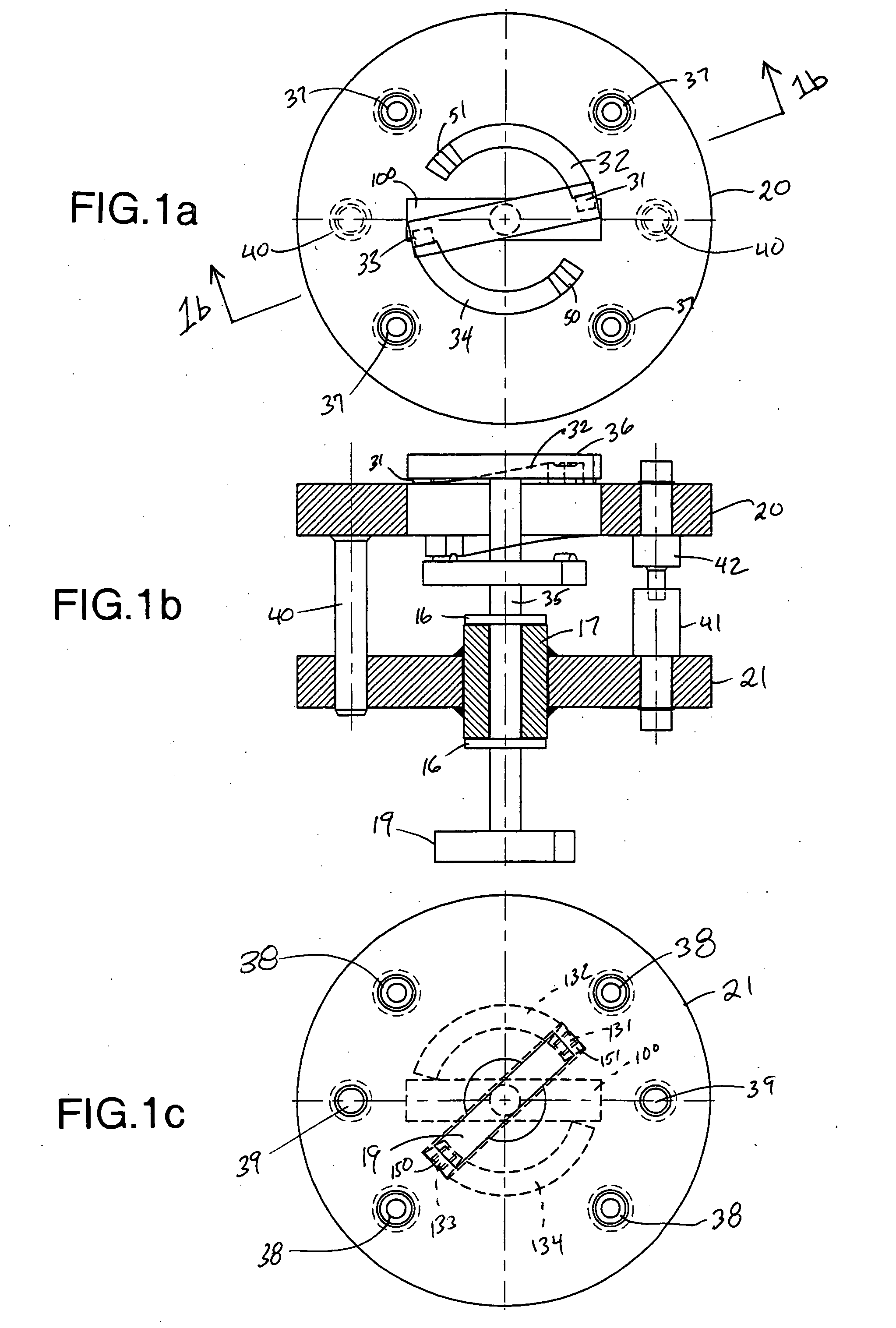
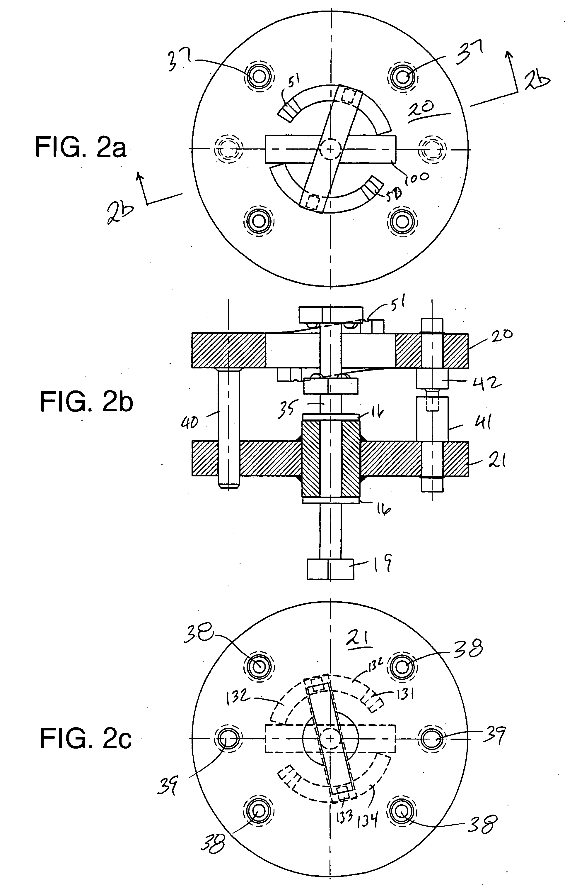
[0028] Referring to FIG. 1 of the drawings, a first manifold plate or junction plate 20 is shown having a plurality of cylindrical apertures 37 for connection of male coupling members 42 thereto. Typically, at least two male coupling members are attached to the first junction plate, which is typically the rear junction plate. A male hydraulic line is connected to one end of each male coupling number 42 while the other end of each male coupling member is configured to mate with female coupling member 41 and establish fluid flow therebetween. The second manifold plate or junction plate 21 includes a plurality of cylindrical apertures 38 for connection of female coupling members 41 thereto. In a preferred embodiment, the second manifold plate is the front plate. Various means may be used to connect the male and female coupling members to the junction plates, as is well known in the art.

[0029] One or more guidepins 40 are provided on the first manifold plate 20 to align the two manifol...


PUM


Abstract

An apparatus is disclosed for simultaneously moving male and female coupling members attached to manifold or junction plates together or apart. The apparatus includes sloped cam surfaces on the first or rear junction plate, and a central shaft having cam followers that move up the sloped cam surface to urge the two junction plates together, and thereby connect male and female coupling members and corresponding sloped cam surfaces on the opposite side of the first junction plate with cam followers that move across the sloped cam surface to disconnect the coupling members.

Description

BACKGROUND OF THE INVENTION [0001] 1. Field of the Invention [0002] This invention concerns hydraulic couplings used in subsea oil and gas well applications. More particularly, it relates to junction plates used to simultaneously mate a plurality of male and female hydraulic couplings. [0003] 2. Description of the Related Art [0004] Offshore oil and gas exploration and production involves the placement of numerous valves and safety equipment on or near the sea floor. The collection of such equipment on a well is often referred to as a “tree.” Frequently, these devices are hydraulically actuated from a remote location such as a production platform. A bundle of hydraulic lines, known as an umbilical cable, is routed from a control panel on the platform to the subsea tree. For ease of assembly and maintenance, subsea hydraulic couplings are typically provided for joining the hydraulic lines to the tree. Examples of such subsea hydraulic couplings are disclosed in U.S Pat. No. 6,626,207...

Claims


Application Information

Patent Timeline
IPC IPC(8): F16LF16L1/26F16L21/00F16L21/025F16L29/04F16L37/08F16L37/24F16L37/256F16L39/00H01R13/629
CPCE21B33/038Y10S285/92F16L21/025F16L21/00F16L1/26F16L37/08F16L37/24F16L37/256F16L39/00H01R13/62905
Inventor SMITH, ROBERT E. III
Owner NAT COUPLING
Why Eureka
Eureka Blog
Learn More