Eureka AIR delivers breakthrough ideas for toughest innovation challenges, trusted by R&D personnel around the world.

Outdoor LED Lighting Device Structure With Easy Installation Features

Inactive Publication Date: 2015-03-26
WU MING YUAN
View PDF11 Cites 5 Cited by
  • Summary
  • Abstract
  • Description
  • Claims
  • Application Information

AI Technical Summary

Benefits of technology

The present invention provides an outdoor LED lighting device with excellent heat dissipation and waterproof effects that are cost-effective and environmentally friendly. The device has a simplified structure that can be easily installed. It includes a casing, light emitting module, driver module, and supporter. The LED lighting device can be easily installed by the supporter in a housing of the conventional outdoor lamp without having to discard the whole set of the conventional outdoor lamp, thus eliminating the unnecessary waste. The supporter may be a column-like structure or include a threaded rod and a connected block. The LED lighting device may be easy to install the street light by the supporter and replace the conventional bulbs. Furthermore, the solar battery module can be included to lower environmental impact without carbon dioxide emissions during power generation.

Problems solved by technology

However, LEDs would generate comparatively high heat energy, with a result of their high light fades and shortened life span.
This leads to limited applications of LEDs to some extent.
When the outdoor lamp is exposed to outside for a long period of time, the fixing screws may be gradually eroded.
Thus, rain or snow may creep through clearances between the screws and the housing of the outdoor lamp, and enter into the housing to thereby cause electrical short circuit and potential safety problems.
Also, when the LED lamp is lightened over a long period of time, the heat generated by the LED would accumulate in the LED lamp and could not be effectively removed therefrom, bringing the LED to burn out due to overheat.
However, these solutions are either less effective to dissipate the heat, or are expensive and structurally complicated though being effective on heat dissipation.

Method used


Image

  • Outdoor LED Lighting Device Structure With Easy Installation Features
  • Outdoor LED Lighting Device Structure With Easy Installation Features
  • Outdoor LED Lighting Device Structure With Easy Installation Features

Examples


Embodiment Construction

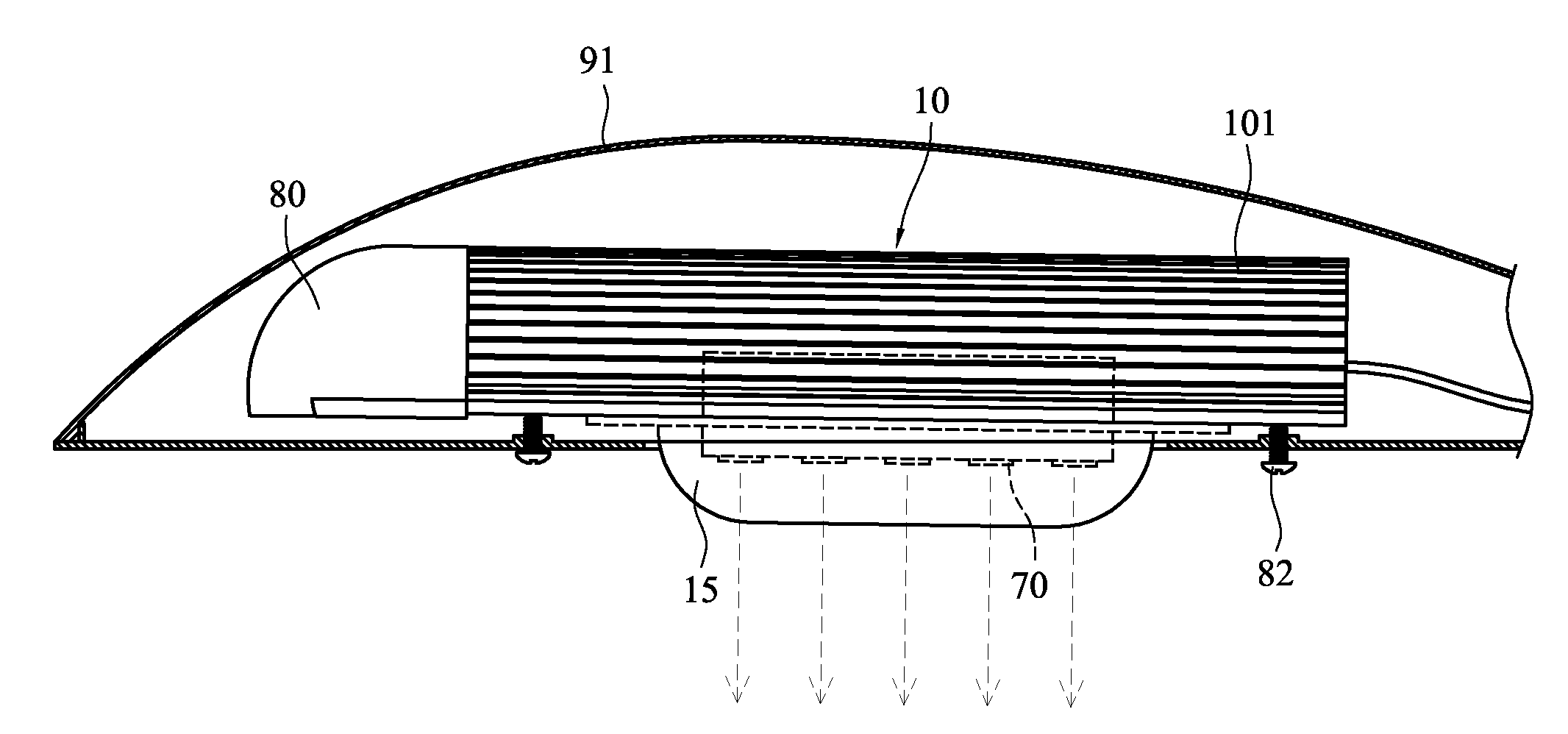
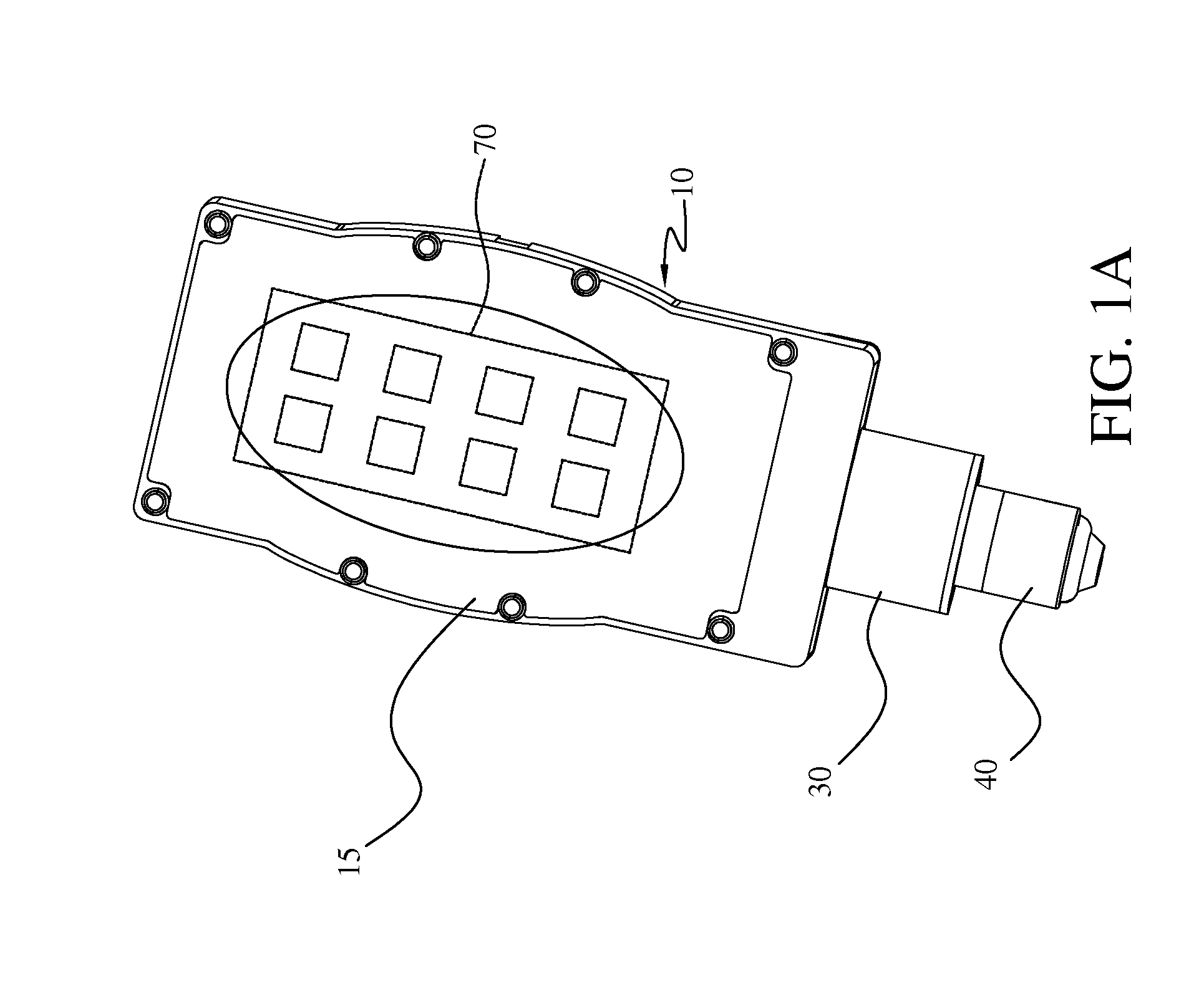
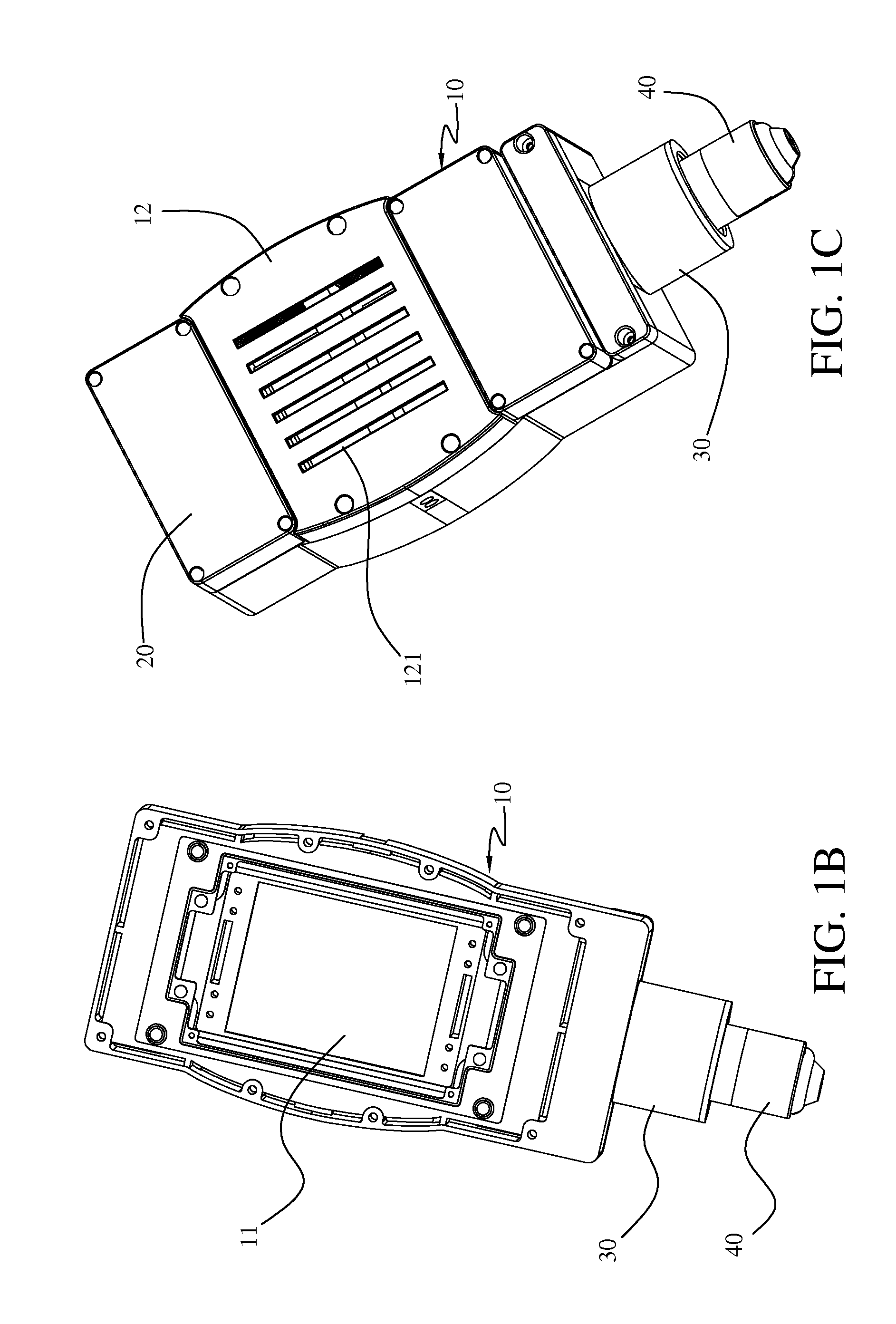
[0031]An outdoor LED(light emitting diode) lighting device of a first embodiment of the present invention is shown in FIGS. 1A, 1B to 1C. The outdoor LED lighting device including a casing 10, a light emitting module 70, a driver module 20 and a connecting module 30. A hollow space 11 is provided in the casing 10. The light emitting module 70 is detachably disposed in the hollow space 11 of the casing 10 and contacted to a radiator 60 disposed therein, also see FIG. 3B. The driver module 20 is detachably disposed in the casing 10 and adjacent to the light emitting module 70. The connecting module 30 is disposed on the casing 10 and electrically connected to the driver module 20 and a connecting base 40 of the the conventional outdoor lamp to replace the conventional bulbs. The connecting module 30 may be detachable and changeable with different type to connect to the connecting base 40, such as screw type or plug type. As shown in FIG. 1A, the connecting module 30 and the connecting...


PUM


Abstract

An outdoor LED lighting device includes a casing, a light emitting module, a driver module and a supporter. This LED lighting device may be installed easily by the supporter in a housing of the conventional outdoor lamp without having to discard the whole set of the conventional outdoor lamp, thus eliminating the unnecessary waste, in achieving cost-effectiveness and environment protection. Also, the LED lighting device has good characteristics of thermal dissipation and waterproof. Moreover, the solar battery module may be included to lower environmental impact without carbon dioxide emissions during power generation.

Description

RELATED-APPLICATIONS[0001]This application is a continuation-in-part of U.S. patent application Ser. No. 13 / 910,239, filed Jun. 5, 2013. This application claims priority to all the above-referenced applications.BACKGROUND OF THE INVENTION[0002]1. Field of Invention[0003]The present invention relates to a light-emitting diode (LED) lamp and a street lamp using the same, and, more particularly, but not exclusively to an outdoor LED lighting device structure with easy installation features.[0004]2. Related Art[0005]As a solid state light source, LEDs (light-emitting diodes) are a product with long life span, firm structure, low power consumption and flexible dimension such that they are becoming to take the place of conventional high pressure halide lamps in a wide range of lighting applications. However, LEDs would generate comparatively high heat energy, with a result of their high light fades and shortened life span. This leads to limited applications of LEDs to some extent.[0006]Le...

Claims


Application Information

Patent Timeline
IPC IPC(8): F21V15/01
CPCF21V15/011F21V23/007F21W2131/103F21V29/74F21K9/23F21V15/01
Inventor WU, MING-YUAN
Owner WU MING YUAN
Why Eureka
Eureka Blog
Learn More