Eureka AIR delivers breakthrough ideas for toughest innovation challenges, trusted by R&D personnel around the world.

Calibration Apparatus and Method for Fluorescent Imaging

Active Publication Date: 2008-04-03
JOHNSON & JOHNSON CONSUMER COPANIES
View PDF19 Cites 13 Cited by
  • Summary
  • Abstract
  • Description
  • Claims
  • Application Information

AI Technical Summary

Benefits of technology

[0005]Other aspects, features and advantages of the present invention will be apparent from the detailed description of the invention that follows.

Problems solved by technology

Variations in illuminating light can result in variations in the digital images captured which are not attributable to skin condition changes, thereby lessening the probative value of digital imaging analysis.

Method used


Image

  • Calibration Apparatus and Method for Fluorescent Imaging
  • Calibration Apparatus and Method for Fluorescent Imaging
  • Calibration Apparatus and Method for Fluorescent Imaging

Examples


Embodiment Construction

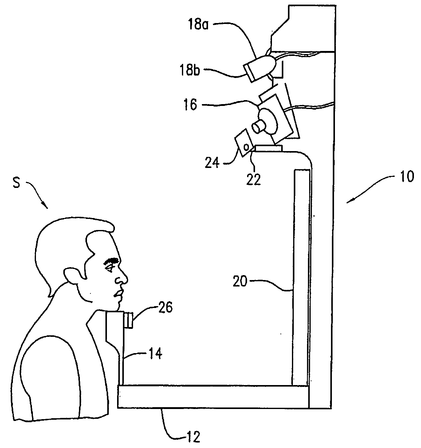
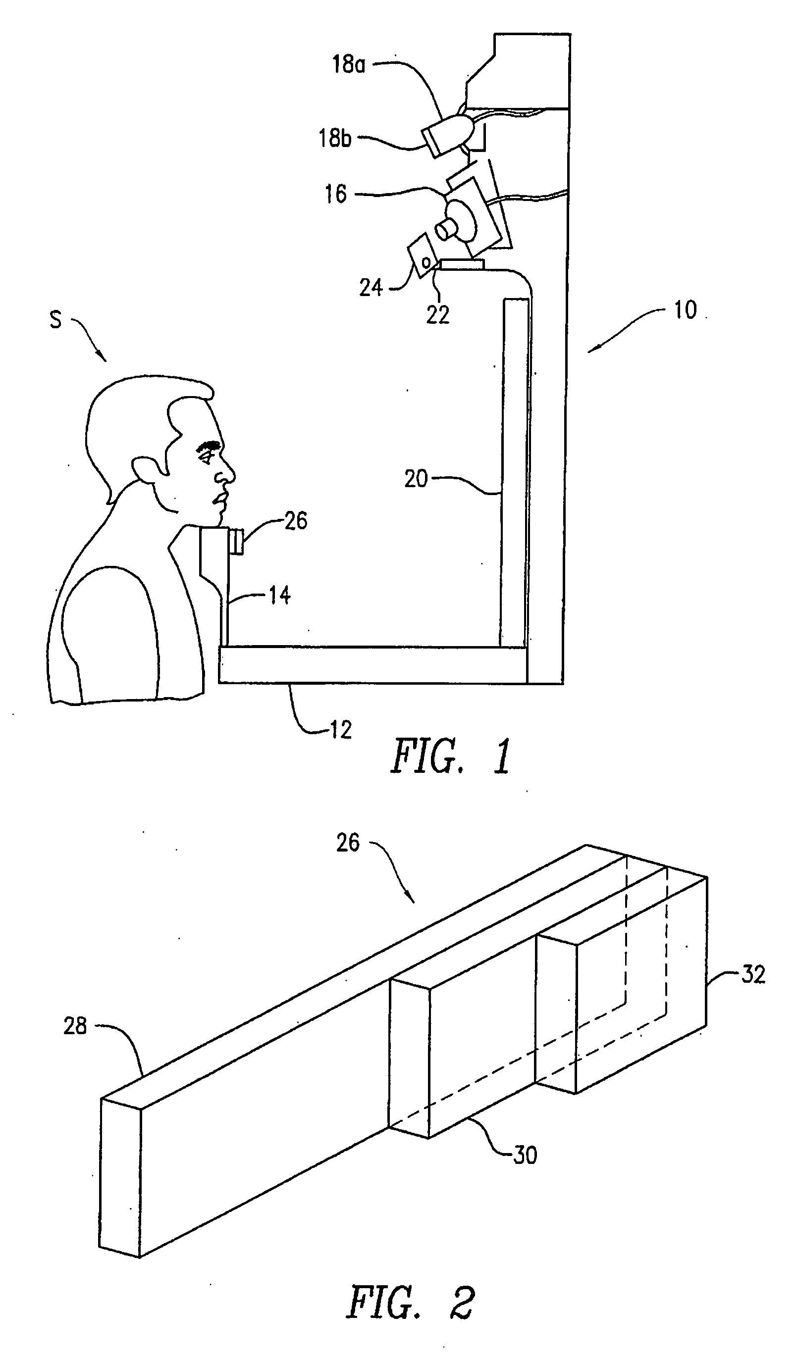
[0010]The present invention includes an apparatus and method for calibration of a skin imaging station. The calibration apparatus includes a fluorescence standard with a first layer made of material having fluorescent properties similar to that of skin when exposed to UV and / or blue light. Additional layers made of translucent material that partially overlay the first layer attenuate the fluorescence intensity of the first layer producing a multi-step calibration standard.

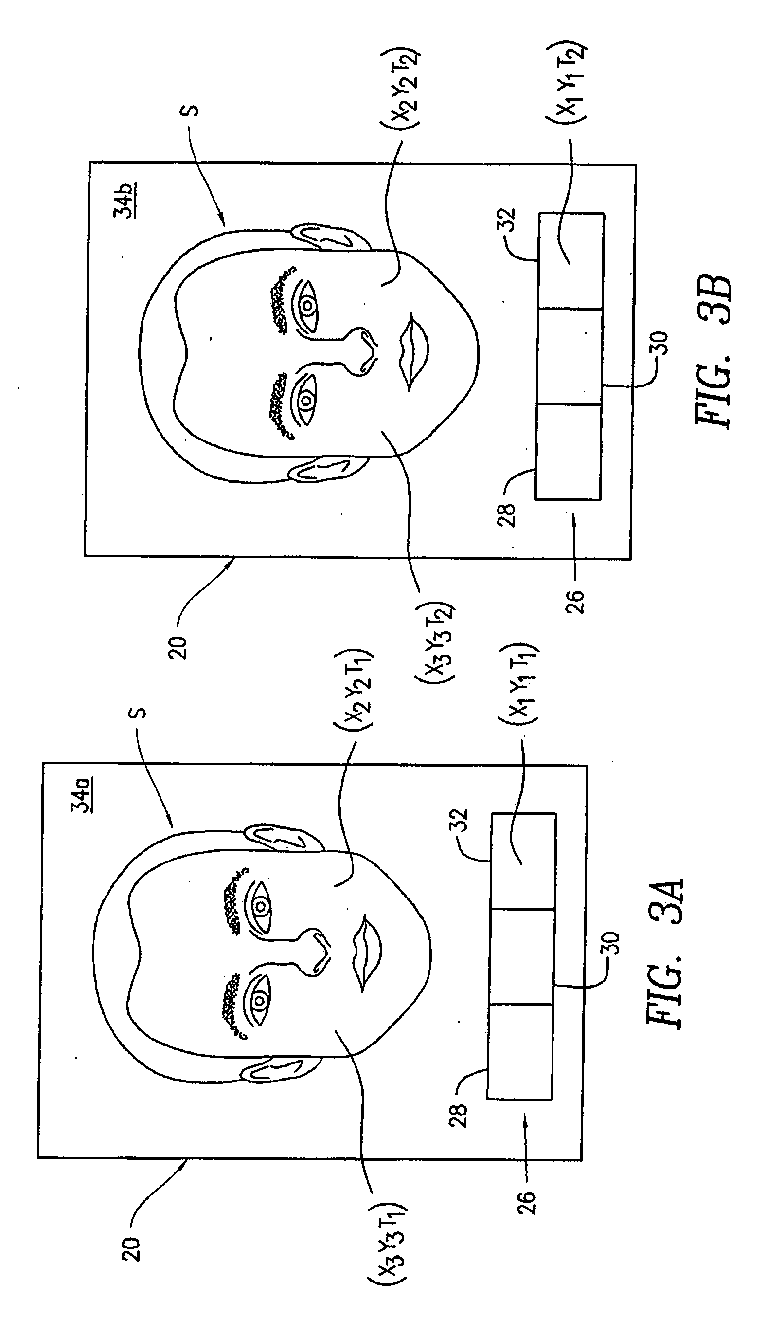
[0011]In accordance with a method of the present invention, the calibration standard is positioned proximate the subject's face, is photographed with the subject and appears in the same photographic image. On taking a UV or blue fluorescence photograph, the different portions of the calibration standard having different numbers of layers absorb the UV and / or blue light and fluoresce at different, known levels, providing multiple fluorescence standards for calibration. A plurality of digital images are recorded for ...


PUM


Abstract

A fluorescence standard for identifying variations in illumination during imaging has a composite fluorescent laminar structure, which fluoresces in response to light in the approximate wavelength range of 375 nm to 430 nm. The fluorescent object has at least two areas with different fluorescent response, e.g., a first made from a strongly luminescing material, such as GG420 filter glass. A portion of the GG420 glass is covered by filter glass having an attenuating effect on the fluorescent response. In accordance with a method of the present invention, variations in illumination during imaging with a camera are detected by placing the standard before the camera during imaging. Each captured image may contain the image of the standard and the fluorescent response of the standard in different images can be compared to identify any response changes due to variations in illumination. The variations in illumination can then be remediated by adjusting the source of illumination, the camera or ambient lighting. Alternatively, the images can be normalized through digital image processing.

Description

CROSS-REFERENCE TO RELATED APPLICATIONS[0001]This application claims the benefit of U.S. Provisional Patent Application Ser. No. 60 / 848,707 filed Oct. 2, 2006, the disclosure of which is incorporated herein by reference in its entirety.FIELD OF THE INVENTION[0002]The present invention relates to an apparatus and method for calibrating skin imaging systems, and more particularly, for calibrating skin imaging systems in which the skin is photographed under UV and / or blue light resulting in a fluorescent image.BACKGROUND OF THE INVENTION[0003]Various imaging systems have been proposed that photographically capture images of a person's face for analysis of the health and aesthetic appearance of the skin. Different images, captured at different times or under different lighting conditions can be used and / or compared to one another to gain insight into the condition of the skin and its response to treatment. This was typically done by human operators inspecting the photographs to identify...

Claims


Application Information

Patent Timeline
IPC IPC(8): G06K9/40A61B1/06G03B17/08G06V10/143
CPCA61B5/0071A61B5/441A61B2560/0233G01N21/278G06K9/2018G01N21/6486G03B15/06G06K9/00255G01N21/6456G01N21/27G01N21/64H04N17/02G06V10/10G06V40/166G06V10/143
Inventor POTE, JEFFREYPAYONK, GREGORYKOLLIAS, NIKIFOROSJACKSON, DICK
Owner JOHNSON & JOHNSON CONSUMER COPANIES
Why Eureka
Eureka Blog
Learn More