Sealer tape and clip assembly

a technology of adhesive tape and assembly, which is applied in the direction of roofs, transportation and packaging, vehicle arrangements, etc., can solve the problems of disadvantageous two-step process of prior art adhesive tape assemblies, and achieve the effect of reducing the cost of adhesive tape assemblies and advantageous installation

Inactive Publication Date: 2005-09-29
GM GLOBAL TECH OPERATIONS LLC
View PDF6 Cites 5 Cited by
  • Summary
  • Abstract
  • Description
  • Claims
  • Application Information

AI Technical Summary

Benefits of technology

[0006] The clip assembly in accordance with the present invention advantageously combines the sealer tape member and clip body in a single assembly. The clip body embeds into the sealer tape member before installation. The clip body may also include a self-centering feature for cross car positioning to avoid the use of a fixture. The resulting one-piece assembly may be advantageously installed in a single-step process. Through the heat cycle of the painting process, the sealer tape melts and embeds the clip body, creating a structural bond between the clip body, the sealer tape and the base material of the recess. This structural bond eliminates the use of the separate structural adhesive tape or double-sided tape used in the prior art processes. The clip body provides a mechanical fastener for the molding member to enclose the recess. The clip assembly in accordance with the present invention combines the two-step process into one by creating the one-piece assembly. The clip assembly eliminates the use of a structural adhesive tape since the overlap bond of the sealer tape member and the clip body replaces the function of the structural adhesive tape, which reduces the cost of the clip assembly.

Problems solved by technology

Each of the above-mentioned prior art clip assemblies disadvantageously require a two-step process because the sealant and the clip assembly are installed separately.

Method used


Image

  • Sealer tape and clip assembly
  • Sealer tape and clip assembly
  • Sealer tape and clip assembly

Examples


first embodiment

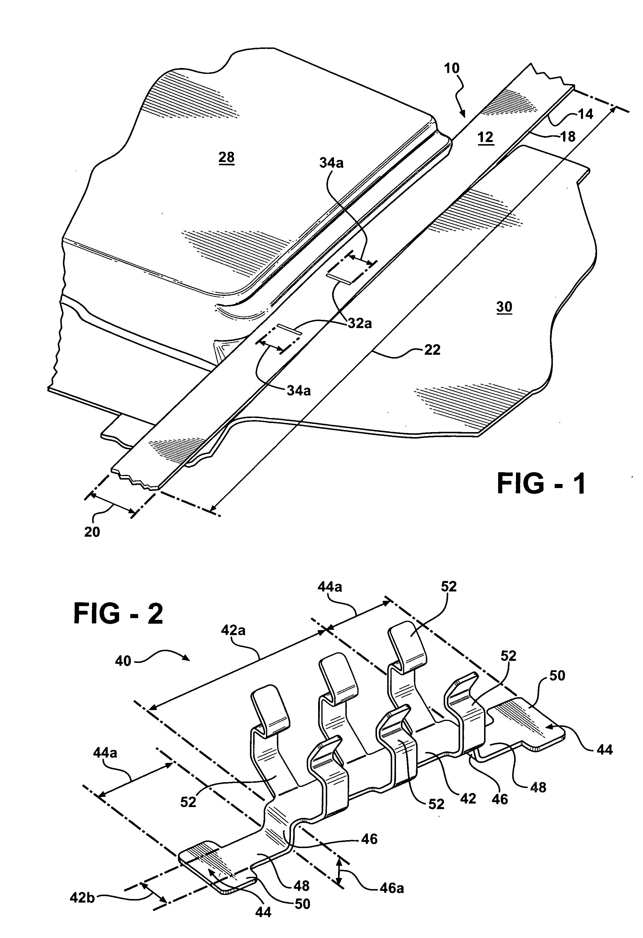
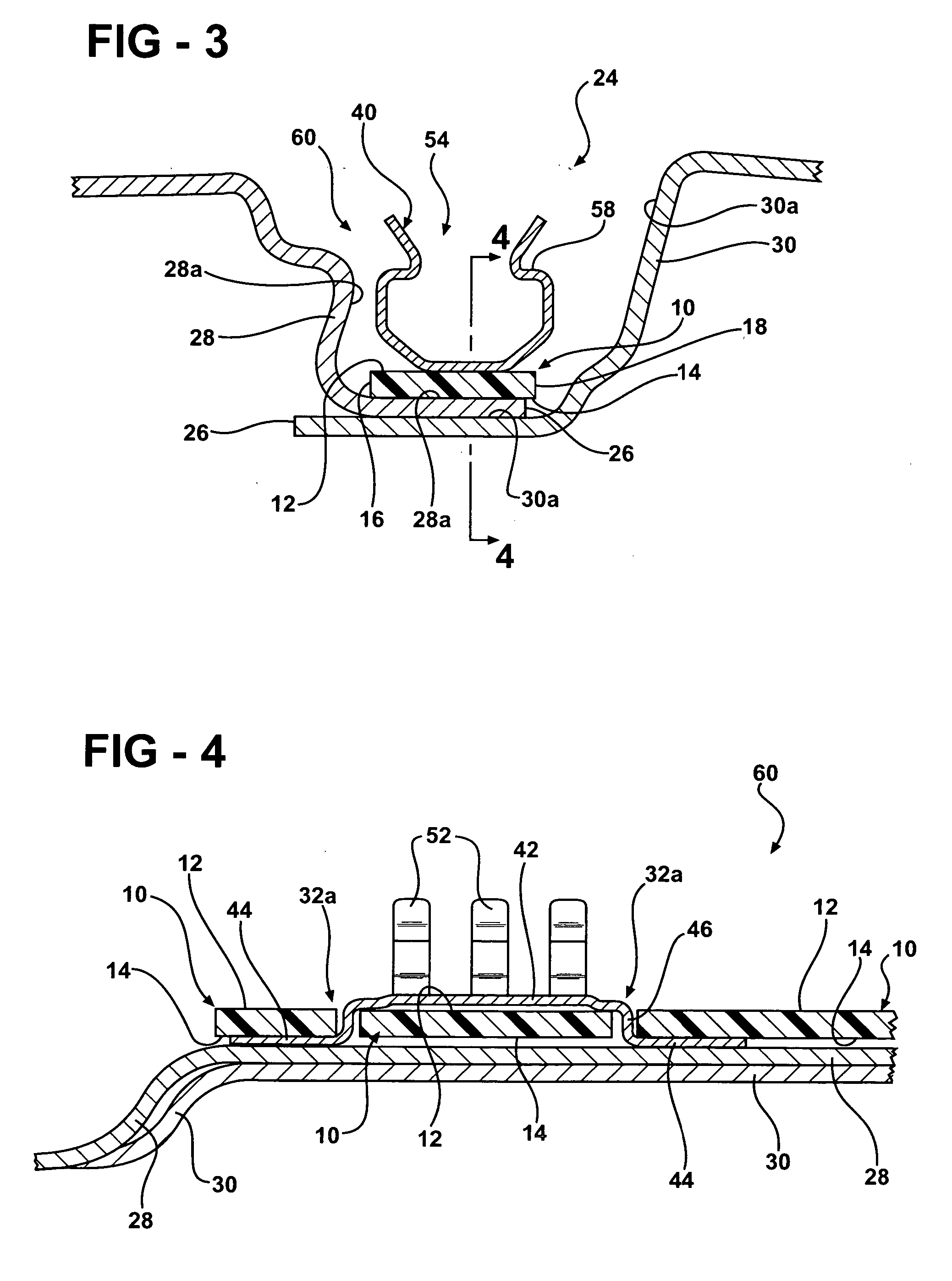
[0015] Referring now to the first embodiment shown in FIGS. 1-4, a sealer tape member in accordance with the present invention is indicated generally at 10. The sealer tape member 10 includes an upper surface 12, a lower surface 14, and opposed side surfaces 16 and 18. The sealer tape member 10 is preferably constructed of a polymer or co-polymer material, such as ethylene vinyl acetate co-polymer, or a similar type material. The sealer tape member 10 has a width indicated by an arrow 20 and a length indicated by an arrow 22. The length 22 of the sealer tape member 10 is significantly greater than the width 20 of the sealer tape member 10. The sealer tape member 10 is adapted to be disposed in a recess 24, best seen in FIG. 3, extending along joined edges 26 of a first body panel 28 and a second body panel 30. Preferably, the body panels 28 and 30 are vehicle body panels, such as a vehicle body panel and a vehicle roof panel having the recess 24 formed therebetween. The recess 24 is...

second embodiment

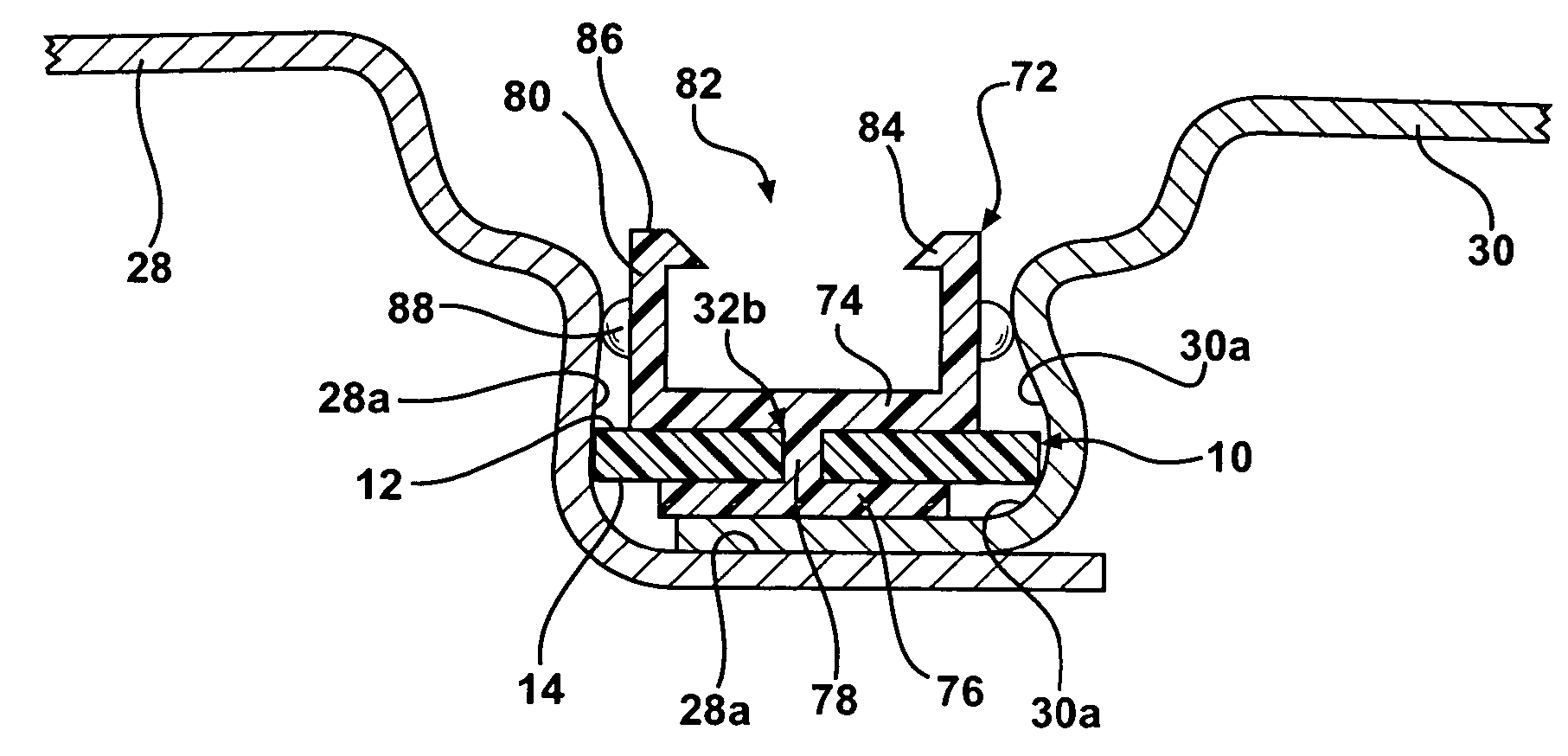
[0020] Referring now to the second embodiment shown in FIGS. 5-7, the sealer tape member 10 includes an aperture 32b formed therein that extends through the upper surface 12 and the lower surface 14. The aperture 32b is disposed between but does not extend through the opposed side surfaces 16 and 18 of the sealer tape member 10. The aperture 32b has a length indicated by an arrow 34b and a width (not shown). The length 34b of the aperture 32b is greater than the width of the aperture 32b, and the length 34b of the aperture 32b extends substantially parallel to the length 22 of the tape member 10 and substantially perpendicular to the width 20 of the tape member 10.

[0021] An alternative embodiment of a sealer tape and clip body assembly in accordance with the present invention is indicated generally at 70. The assembly 70 includes a clip body 72 having an elongated, generally rectangular and substantially planar upper portion 74 having a length indicated by an arrow 74a, and an elong...


PUM


Abstract

A sealer tape and clip assembly in accordance with the present invention is adapted to be disposed in a recess, defined by at least one interior surface. The assembly includes a sealer tape member having an upper surface, a lower surface, and opposed side surfaces. An aperture extends through the upper surface and the lower surface, and is disposed between but does not extend through the opposed side surfaces. A clip body includes an upper portion, a lower portion, and an intermediate portion extending therebetween. The intermediate portion of the clip body is disposed in the aperture, the upper portion of the clip body engages the upper surface of the sealer tape member, and the lower portion of the clip body engages the lower surface of the sealer tape member. The sealer tape member sealingly bonds with the interior surface of the recess to secure the assembly in the recess.

Description

BACKGROUND OF THE INVENTION [0001] The present invention relates generally to molding assemblies and the like and, in particular, to a sealer tape and clip assembly. [0002] Moldings, which are placed in a recess such as a recess between adjoining body panels in an automobile body, are well known. Moldings are utilized for minimizing water and / or foreign object intrusion into the recess as well as for the aesthetic purpose of covering the recess from the customer's view in the final product. [0003] Typically, moldings are attached to the automobile body by a clip assembly or the like disposed in the recess. One type of prior art clip assembly uses a one-piece plastic clip and structural adhesive tape assembly, installed on top of a pumpable flow sealer in the recess. The pumpable flow sealer, which prevents water leakage at the weld joint, is applied manually to the recess prior to the installation of the clip assembly. The heat cycle during the paint process activates the structural...

Claims


Application Information

Patent Timeline
Patent Type & Authority Applications(United States)
IPC IPC(8): B60R13/02B60R13/04B62D27/00
CPCB60R13/04
Inventor HUI, PAULFLOAREA, GEORGE C.
Owner GM GLOBAL TECH OPERATIONS LLC
Why Eureka
Try Eureka