Fiber preparation machine

Pending Publication Date: 2022-02-10
MASCHINENFABRIK RIETER AG
View PDF9 Cites 0 Cited by
  • Summary
  • Abstract
  • Description
  • Claims
  • Application Information

AI Technical Summary

Benefits of technology

The patent describes a device that allows for optical recording of fiber material surfaces during processing. A light source is directed into the store or filling chute, and a camera is placed inside or outside the chute. The camera is protected from environmental influences by a transparent boundary. The device can be used in various fiber processing machines and allows for continuous monitoring of fiber material quality during the removal process. The technical effects include matching the frequency range of the light source and camera, maximizing illuminance, and simplifying the design for easy installation and maintenance.

Problems solved by technology

The disadvantage of these devices is that a fiber material flow is necessary and only foreign material can be detected.
A statement regarding the quality or condition of the fiber material is not possible, however, since no recording of the entire flow of fiber material takes place.
Another disadvantage of this device is that it is not possible to make a statement regarding the quality or condition of the fiber material, since no recording of the entirety of the fiber material takes place, and impurities are instead only searched for in a targeted manner.
The disadvantage of these devices is that they provide a detection and analysis of the substances that are to be removed from the process or are already removed, but cannot make any statement regarding the fiber material remaining in the process.
Also, an action that is carried out on the basis of the provided measures only leads to consequences (optimization or improvement) in the process in the affected machine or possibly in a subsequent machine in the process sequence.
The disadvantage of the device is that the processes can only be assessed within the machine casing, but not within the machine itself.
The disadvantage of this is that this procedure is time-consuming and the results of the analysis are available with a time delay and do not reflect the current status.
Tests in the laboratory are very time-consuming and thus only a few samples are taken, which means that there is still a high level of uncertainty in the results.

Method used


Image

  • Fiber preparation machine
  • Fiber preparation machine

Examples


Embodiment Construction

[0028]Reference will now be made to embodiments of the invention, one or more examples of which are shown in the drawings. Each embodiment is provided by way of explanation of the invention, and not as a limitation of the invention. For example features illustrated or described as part of one embodiment can be combined with another embodiment to yield still another embodiment. It is intended that the present invention include these and other modifications and variations to the embodiments described herein.

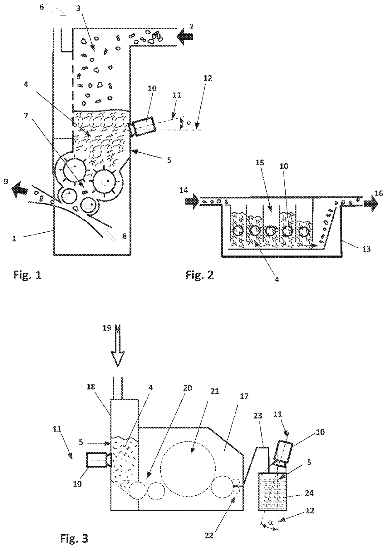
[0029]FIG. 1 is a schematic view of a cleaning machine 1 having a store 3. The fiber material 4 is introduced into the store 3 via pneumatic conveyance through the inlet 2, usually in the form of fiber flocks. In the upper region of the store 3, the fiber material 4 is separated from the transport air and the transport air is discharged from the store 3 as exhaust air 6. The fiber material 4 collects in the lower region of the store 3. The fiber material 2 is removed again from the...


PUM

PropertyMeasurementUnit
Angleaaaaaaaaaa
Areaaaaaaaaaaa
Illuminanceaaaaaaaaaa

Abstract

A fiber preparation machine for processing fiber material includes a store or filling chute for storing the fiber material before or after processing. A camera is directed into an interior of the store or filling chute, the camera having an optical axis oriented at an angle (α) with respect to a vertical axis that is perpendicular to a surface of the fiber material in a range of plus 30 degrees to minus 30 degrees. The camera has a resolution for detecting a particle having an extension of 0.1 mm2 on the surface of the fiber material.

Description

FIELD OF THE INVENTION[0001]The invention relates to a novel fiber preparation machine for processing fiber material.BACKGROUND[0002]In a fiber preparation system in a spinning mill, supplied fiber material in the form of fibers or fiber flocks is prepared for use in a spinning machine by fiber preparation machines. In a fiber preparation system, the fibers to be prepared for spinning pass through a plurality of processing stages. In a first stage, the fibers are removed from fiber bales in the form of fiber flocks. What are referred to as bale openers are usually used for this purpose. These fiber flocks are transported out of the bale opener by means of pneumatic fiber flock conveyance and are, for example, transferred to a downstream cleaning machine. In the further stages, the fiber preparation system also has a sequence of cleaning machines through which the fibers or fiber flocks pass. The sequence and design of the cleaning machines are adapted to the fibers to be processed a...

Claims


Application Information

Patent Timeline
IPC IPC(8): D01G31/00D01G23/04
CPCD01G31/00D01G15/40D01G23/04G01N21/8915D01G13/00D01G15/02D01G31/006G01N21/85G01N2021/8592
Inventor GRIESSHAMMER, CHRISTIANWOLFER, TOBIASCEVONA, PETR
Owner MASCHINENFABRIK RIETER AG
Why Eureka
Try Eureka