Dielectric optical fibre cable with improved mounting characteristic

A cable and optical fiber technology, applied in the field of dielectric optical fiber cables, can solve problems such as performance degradation and low installation performance

Inactive Publication Date: 2006-07-12
PRYSMIAN CAVI E SISTEMI ENERGIA +1
View PDF3 Cites 2 Cited by
  • Summary
  • Abstract
  • Description
  • Claims
  • Application Information

AI Technical Summary

Problems solved by technology

Those skilled in the art know that cables based on this structure may have reduced performance with respect to the maximum cable length that can be introduced in the bushing, the installation performance is even lower than when using the blowing technique

Method used


Image

  • Dielectric optical fibre cable with improved mounting characteristic
  • Dielectric optical fibre cable with improved mounting characteristic
  • Dielectric optical fibre cable with improved mounting characteristic

Examples


Embodiment Construction

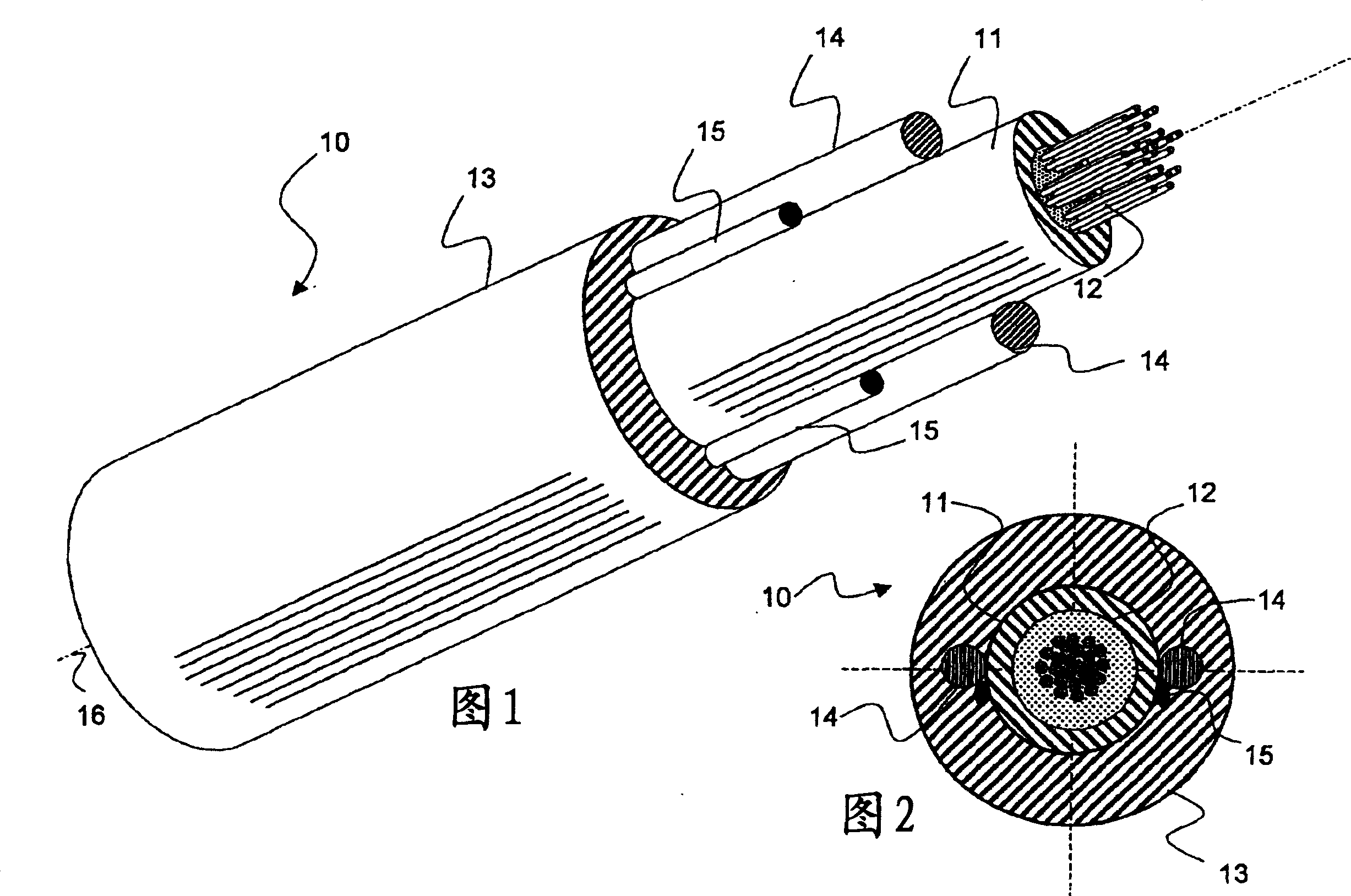
[0044] 1 and 2, a dielectric fiber optic cable 10 according to the present invention at least includes: a core sleeve 11 containing an optical fiber 12, a plastic sheath 13 surrounding the core sleeve 11, a pair of straight lines at least partially embedded in the sheath 13 extended, diametrically opposed dielectric rods 14, wherein the rods 14 have a compressive stiffness effective to resist substantial contraction of the cable, and effective to receive tensile loads without substantial transfer of the tensile loads to the optical fiber 12 of tensile stiffness. The cable according to the invention may also comprise a sheath cutting element 15 for cutting the sheath 13 at the end of the cable for easy access to the optical fibers. The cable 10 has a longitudinal axis 16 .

[0045] Preferably, said rods comprise filamentous strands of glass and / or aramid fibres, more preferably they are made of GRP (glass reinforced plastic) or ARP (aramid reinforced plastic). Furthermore, th...


PUM


Abstract

A telecommunication optical fiber cable and in particular a reduced diameter optical cable with improved installation features for use in the end part of an access telecommunication network. The optical fiber cable comprising: a number of optical fibers; at least a core tube containing the optical fibers; a jacket surrounding the core tube; and at least one strength rod spaced from the central axis, the cable having a twisting stiffness G * J p , wherein G is the elastic shear modulus; and J p is the polar moment of inertia of a cable section, wherein the twisting stiffness G * J p is lower than, or equal to, 0,10 Nm<2>, preferably lower than, or equal to, 0,05 Nm<2> and more preferably lower than, or equal to, 0,02 Nm<2>. The cable is profitably installable by a blown method.

Description

technical field [0001] The present invention relates to telecommunications fiber optic cables, and more particularly to reduced diameter dielectric fiber optic cables with improved installation features for use in terminal sections of access telecommunications networks. Background technique [0002] Access telecommunication networks formed by copper wires are being replaced by fiber optic networks due to the large bandwidth capacity of fiber optic networks. Since this replacement is determined by a valid end-client request and is quite expensive for telecom providers, some providers are often accustomed to arrange access networks formed only of empty plastic pipes and only when The fiber optic cable is placed in the duct only when properly requested by the end. Such access network fibers may comprise a smaller number of fibers, typically 2÷12, 24, 48 or 72. [0003] A suitable technique for installing these cables in ducts is the "blown method": the fiber optic cables are ...

Claims


Application Information

Patent Timeline
Patent Type & Authority Applications(China)
IPC IPC(8): G02B6/44
CPCG02B6/4433
Inventor 玛斯莫·皮佐诺阿莱桑德罗·基诺齐奥基奥凡尼·布兰迪
Owner PRYSMIAN CAVI E SISTEMI ENERGIA
Why Eureka
Try Eureka