Detecting the status of an electrical fuse

a technology for detecting the status of electrical fuse, applied in the direction of fuses testing, fault location, instruments, etc., can solve the problem of inability to adjust the sensitivity of the fuse circuit to detect the resistance value of the fuse, the timing of the latch trip lacks control, and the control signals mrsb>1/b> and mrsb>2/b> opera

Inactive Publication Date: 2005-09-29
TAIWAN SEMICON MFG CO LTD
View PDF11 Cites 16 Cited by
  • Summary
  • Abstract
  • Description
  • Claims
  • Application Information

AI Technical Summary

Benefits of technology

[0005] A further advantage of the invention, is that a poly fuse under detection is in a bridge circuit that is adjustable in sensitivity to the fuse status data, to avoid confusion b

Problems solved by technology

Because of difficulty to predict the slope of the inverter decay voltage, the timing of the latch trip lacks control.
The fuse circuit is unable to adjust its sensitivity to detect the fuse resistance value.
A disadvantage is that the control signals MRS1 and MRS2 operate by precisely timed steps; precharge, generat

Method used


Image

  • Detecting the status of an electrical fuse
  • Detecting the status of an electrical fuse
  • Detecting the status of an electrical fuse

Examples


Embodiment Construction

[0010] Terms concerning attachments, coupling and the like, such as “connected” and “interconnected,” refer to a relationship wherein structures are secured or attached to one another either directly or indirectly through intervening structures, as well as both movable or rigid attachments or relationships, unless expressly described otherwise.

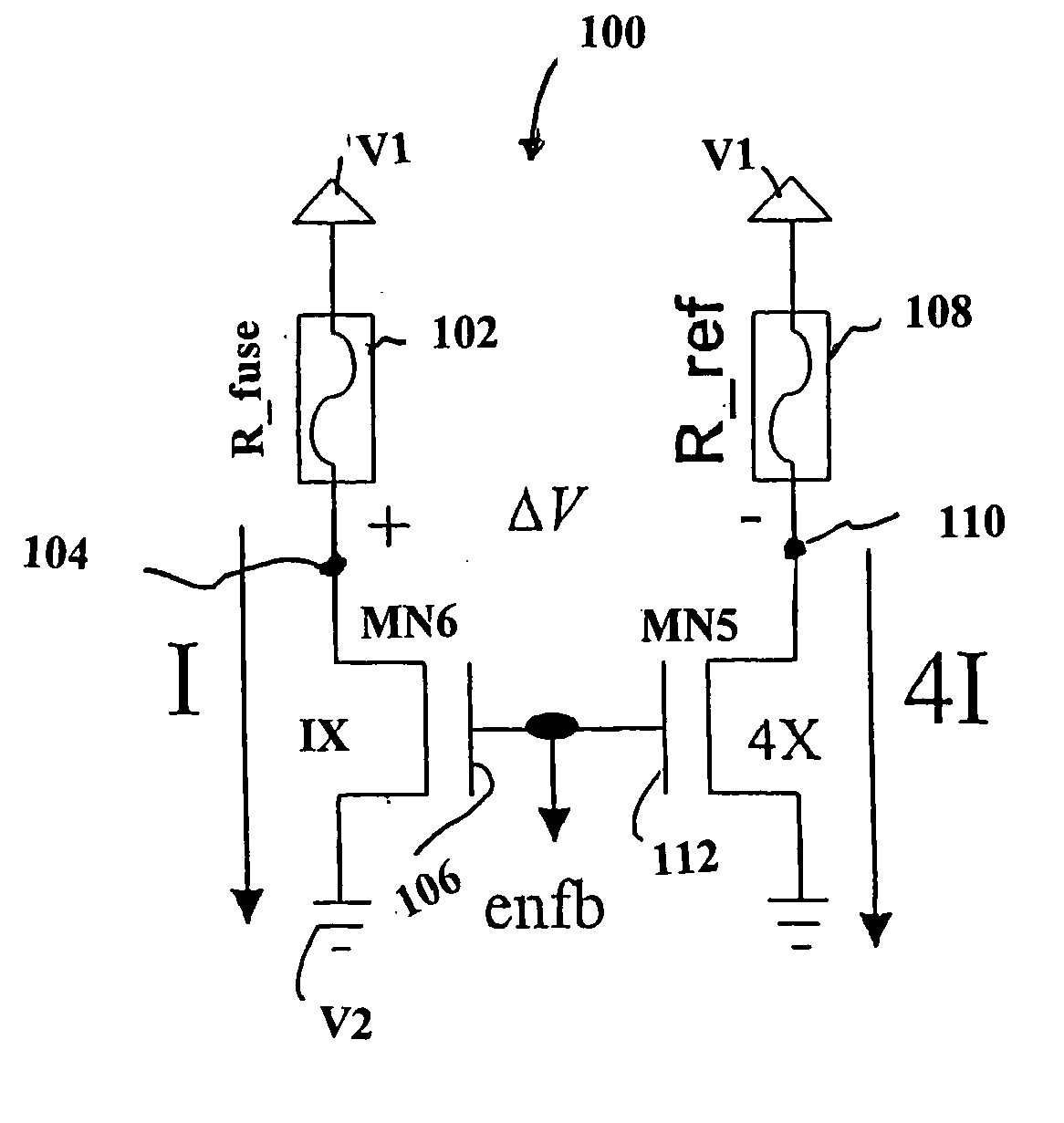
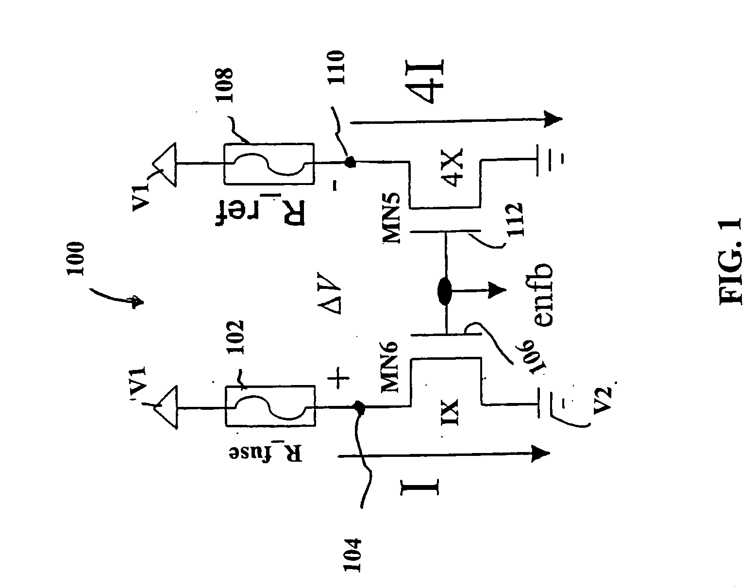
[0011]FIG. 1 discloses a fuse bridge circuit (100) having a fuse resistance R—fuse, of a poly fuse (102) under detection, connected between a first reference voltage V1 and a first node (104). An MN6 transistor (106), for example, an NMOS transistor, has its drain connected to the first node (104), and its source connected to a second reference voltage V2, for example, ground, also referred to as, earth.

[0012]FIG. 1 further discloses fuse resistance R—ref, of a reference poly fuse (108) connected between the first reference voltage V1 and a second node (110). An MN5 transistor (112), for example, an NMOS transistor, has its drain connected t...


PUM


Abstract

A fuse detection circuit has; a fuse (102) under detection to produce a first voltage in the first arm in response to a read signal; a reference fuse (108) to produce a second voltage in response to the read signal; a sensing circuit (124) to sense the first voltage and the second voltage as status value data of the fuse under detection; a latch circuit (136) to keep the data in the sensing circuit; and a timing control circuit (138) to turn off the fuse bridge circuit independently of the read signal.

Description

FIELD OF THE INVENTION [0001] The invention relates to detecting the status of an electrical fuse, and, more particularly, to a method and electrical circuit for testing the status of an electrical fuse in a semiconductor circuit. BACKGROUND [0002] U.S. Pat. No. 6,384,664 discloses a fuse circuit for detecting the resistor difference between a poly fuse under detection and a matching reference fuse, which are in two legs at a top of an electrical bridge circuit. Two more legs at a bottom of the electrical bridge circuit have matched transistors. When the fuse under detection is not burned, the differential voltage across the bridge circuit remains at zero. When the fuse is burned, a comparator detects a transition in differential voltage across the bridge circuit. The comparator has a flip flop latch that will trip and store the data. The differential voltage is impressed on an output of an inverter with a long decay pulse, which delays turn off of the differential voltage before th...

Claims


Application Information

Patent Timeline
IPC IPC(8): G01R31/02G01R31/74G11C17/16G11C29/02H02H7/00
CPCG01R31/07G11C29/027G11C29/02G11C17/16G01R31/74
Inventor WU, JUI-JEN
Owner TAIWAN SEMICON MFG CO LTD
Why Eureka
Try Eureka