Method and apparatus for enhanced autonomous GPS

a technology of autonomous gps and methods, applied in the field of methods and equipment, can solve the problems of large position errors, large range errors of up to 0.8 m, and similar sized errors in the position of gps receivers

Active Publication Date: 2005-09-29
AVAGO TECH INT SALES PTE LTD
View PDF31 Cites 72 Cited by
  • Summary
  • Abstract
  • Description
  • Claims
  • Application Information

AI Technical Summary

Benefits of technology

[0013] A method and apparatus for using long term satellite tracking data in a remote receiver is described. In one embodiment of the invention, long term satellite tracking data is received at a remote receiver from a server. For example, the long term satellite tracking data may include satellite orbit, satellite clock, or satellite orbit and clock information that is val

Problems solved by technology

Absolute timing errors result in range errors of up to 0.8 m for each millisecond of timing error.
These range errors produce a similarly sized error in the GPS receiver position.
Hence, absolute time accuracy of 10 ms is sufficient for position accuracy of approximately 10 m. Absolute timing errors of much more than 10 ms will result in large position errors, and so typical GPS receivers have required absolute time to approximately 10 milliseconds accuracy or better.
It is always slow (no faster than 18 seconds), frequently difficult, and sometimes impossible

Method used


Image

  • Method and apparatus for enhanced autonomous GPS
  • Method and apparatus for enhanced autonomous GPS
  • Method and apparatus for enhanced autonomous GPS

Examples


Embodiment Construction

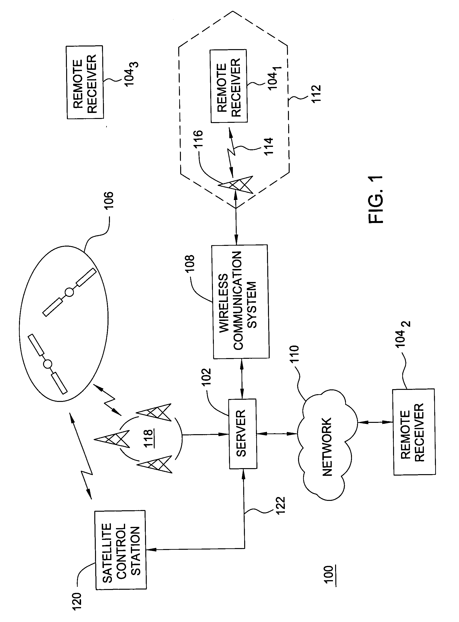
[0029]FIG. 1 is a block diagram depicting an exemplary embodiment of a position location system 100. The system 100 comprises a server 102 and a plurality of remote receivers 104, illustratively, a remote receiver 1041, a remote receiver 1042, and a remote receiver 1043. The remote receivers 104 measure pseudoranges to a plurality of satellites 106 in a constellation of satellites to locate position. For example, the remote receivers 104 may measure pseudoranges to a plurality of global positioning system (GPS) satellites in the GPS constellation. The server 102 distributes data representative of satellite trajectory information, satellite clock information, or both to facilitate operation of the remote receivers 104 (“satellite tracking data”). Notably, the remote receivers 104 may use the satellite tracking data to assist in acquiring satellite signals and / or compute position.

[0030] The server 102 may distribute the satellite tracking data to the remote receivers 104 using a comm...


PUM


Abstract

Method and apparatus for locating position of a remote receiver is described. In one example, long term satellite tracking data is obtained at a remote receiver. Satellite positioning system (SPS) satellites are detected. Pseudoranges are determined from the remote receiver to the detected SPS satellites. Position of the remote receiver is computed using the pseudoranges and the long term satellite tracking data. SPS satellites may be detected using at least one of acquisition assistance data computed using a previously computed position and a blind search. Use of long term satellite tracking data obviates the need for the remote receiver to decode ephemeris from the satellites. In addition, position of the remote receiver is computed without obtaining an initial position estimate from a server or network.

Description

CROSS-REFERENCE TO RELATED APPLICATIONS [0001] This application is a continuation-in-part of co-pending U.S. patent application Ser. No. 10 / 674,267, filed Sep. 29, 2003, which claims benefit of U.S. provisional patent application Ser. No. 60 / 415,364, filed Oct. 2, 2002. Each of the aforementioned related patent applications is herein incorporated by reference.BACKGROUND OF THE INVENTION [0002] 1. Field of the Invention [0003] The present invention generally relates to a position location system and, more particularly, to using long term satellite tracking data in a remote receiver. [0004] 2. Description of the Related Art [0005] Global Positioning System (GPS) receivers use measurements from several satellites to compute position. GPS receivers normally determine their position by computing time delays between transmission and reception of signals transmitted from satellites and received by the receiver on or near the surface of the earth. The time delays multiplied by the speed of ...

Claims


Application Information

Patent Timeline
IPC IPC(8): G01S1/00G01S19/05G01S19/25G01S19/42
CPCG01S19/05G01S19/06G01S19/252G01S19/42G01S19/256G01S19/258G01S19/27G01S19/254G01S19/30
Inventor DIGGELEN, FRANK VANPODSHIVALOV, SERGEIABRAHAM, CHARLES
Owner AVAGO TECH INT SALES PTE LTD
Why Eureka
Try Eureka