Driving circuit for liquid crystal device

Inactive Publication Date: 2005-09-29
SHARP KK
View PDF2 Cites 4 Cited by
  • Summary
  • Abstract
  • Description
  • Claims
  • Application Information

AI Technical Summary

Benefits of technology

[0013] Moreover, the present invention provides a driving circuit for a liquid crystal device, wherein prior to applying voltage to the liquid crystal element, the voltage level corresponding to the display data causes all the analog switches to be set to an off status, so as to prevent overlap of output voltage during transition of the analog switch to the off status and during transition of the analog switch to the on status according to a subsequent display data.
[0014] According to the present invention, the number of transistor elements per one output of the decoder circuit portion constituting the driving circuit for the liquid c

Problems solved by technology

According to this arrangement, there are a number of sharable portions taki

Method used


Image

  • Driving circuit for liquid crystal device
  • Driving circuit for liquid crystal device
  • Driving circuit for liquid crystal device

Examples


Example

[0020] The preferred embodiment of the present invention will now be described.

[0021] An embodiment of the driving circuit for a liquid crystal device according to the present invention will be described with reference to the drawings.

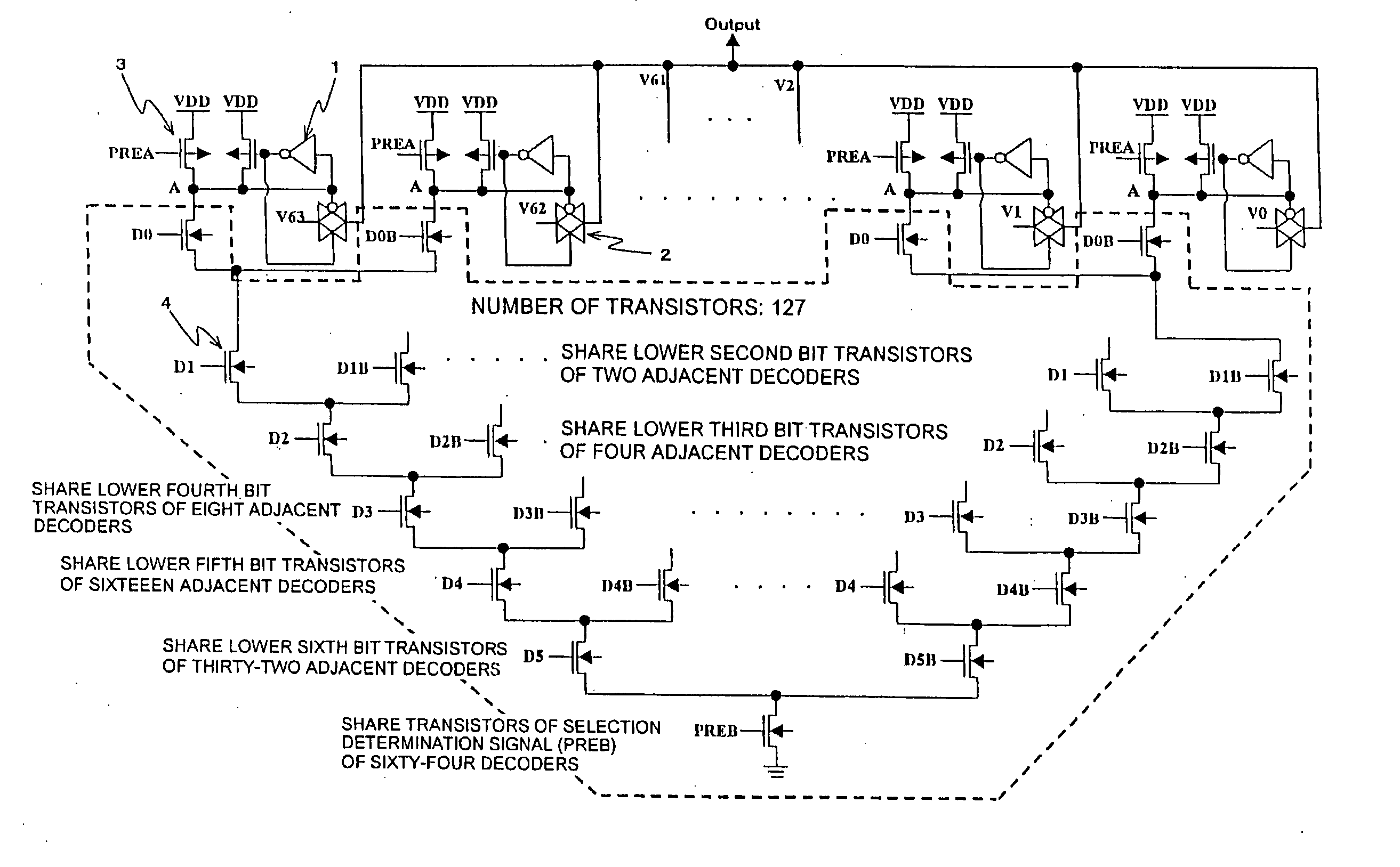
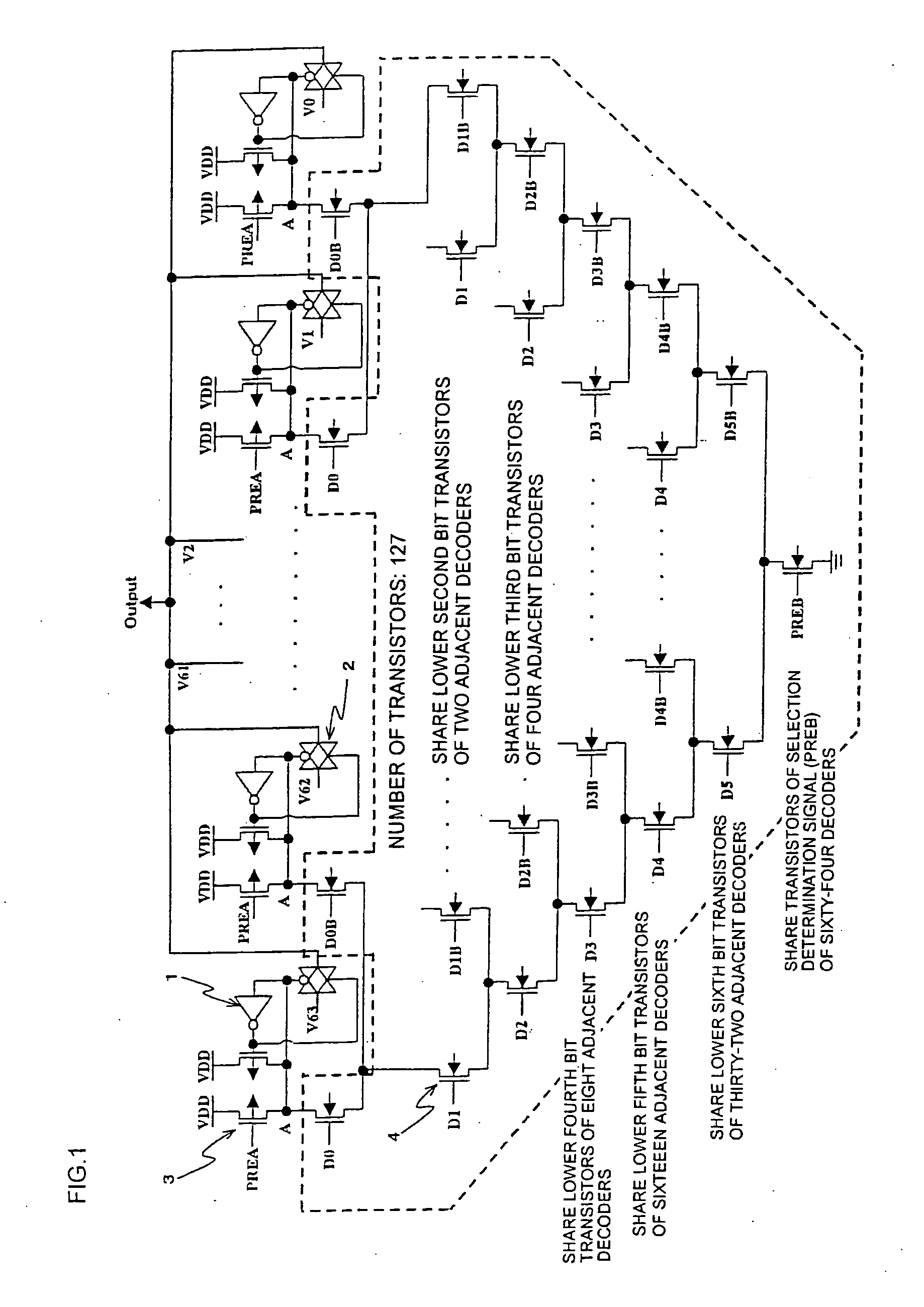
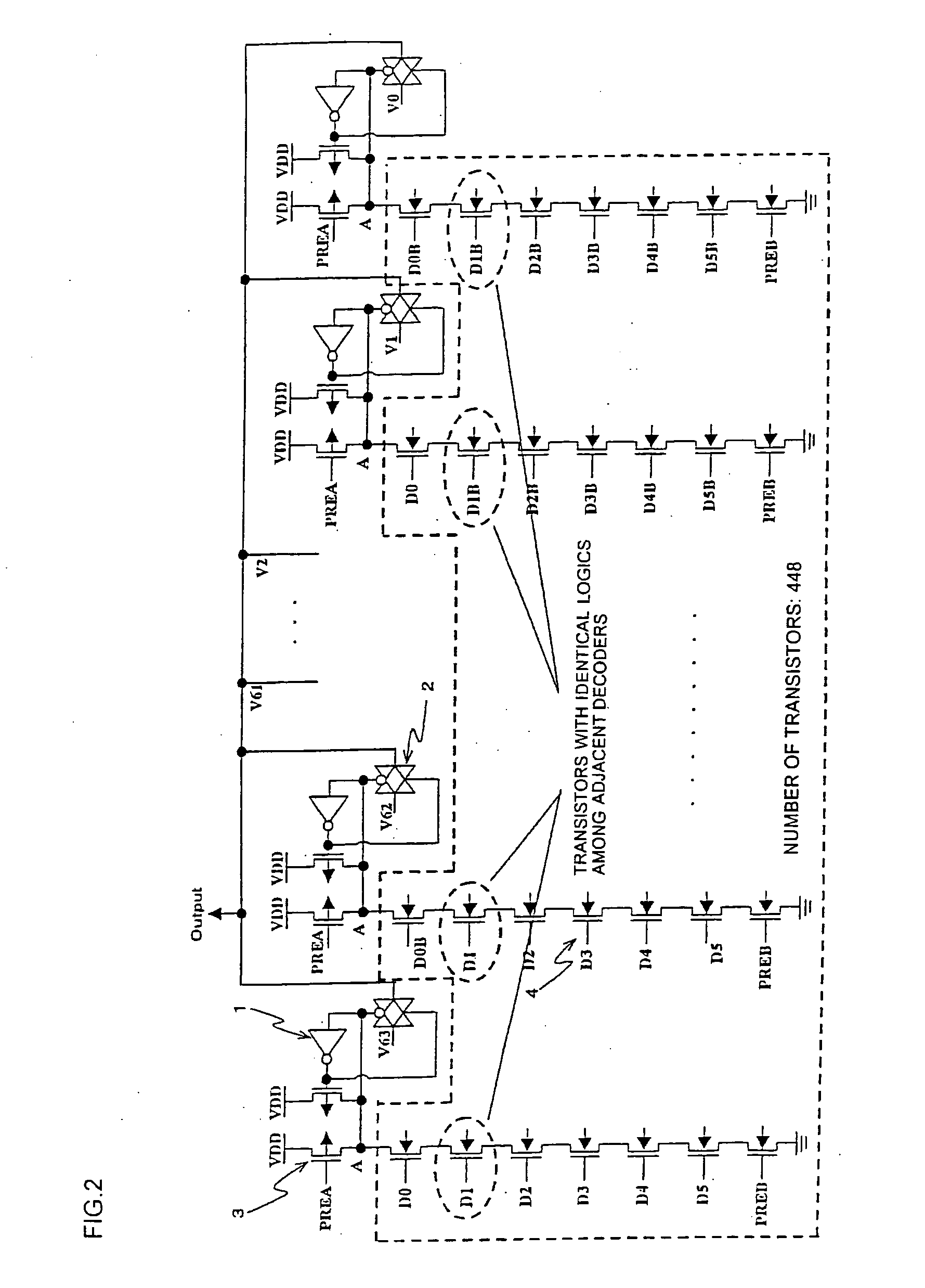
[0022] The driving circuit for a liquid crystal device according to the present invention will be described in comparison with the prior art driving circuit for a liquid crystal device. FIG. 1 is a driving circuit for a liquid crystal device according to the present embodiment, and FIG. 2 shows one example of a prior art driving circuit for a liquid crystal device. The following description refers to a six bit arrangement merely illustrated as an example.

[0023] According to the prior art driving circuit for a liquid crystal device, there are sixty-four voltage levels (V0 through V63), and since a single voltage level is composed of seven transistors, the circuit is composed of:

(sixty-four voltage levels)×(seven transistors)=448 transistors per one o...


PUM


Abstract

The invention provides a driving circuit for a liquid crystal device having a reduced number of transistor elements by sharing transistors having identical logics among adjacent decoders. The driving circuit for a liquid crystal device capable of carrying out gradation display by applying gradation voltage corresponding to a display data to a liquid crystal element comprises a decoder circuit portion composed of a dynamic circuit for selecting the gradation voltage, the decoder circuit portion having a number of transistor elements 4 reduced by sharing transistors with identical logics constituting adjacent decoders. The voltage level corresponding to the display data causes all the analog switches to be set to an off status, so as to prevent overlap of output voltage during a timing of transition of the analog switch to the off status and a timing by which the analog switch is turned on according to a subsequent display data.

Description

[0001] The present application is based on and claims priority of Japanese patent application No. 2004-095134 filed on Mar. 29, 2004, the entire contents of which are hereby incorporated by reference. BACKGROUND OF THE INVENTION [0002] 1. Field of the Invention [0003] The present invention relates to a driving circuit for a liquid crystal device, and specifically, to a driving circuit for a liquid crystal device capable of selecting necessary gradation data by a decoder circuit portion and carrying out gradation display. [0004] 2. Description of the Related Art [0005] The driving circuit for a liquid crystal device according to the prior art will now be described. FIG. 2 shows one example of a prior art driving circuit for a liquid crystal device. If the digital display data input to the driving circuit of the liquid crystal device is a 260,000-color display data composed of RGB (three primary colors, which are R (red), G (green) and B (blue)) each represented by six bits, there wil...

Claims


Application Information

Patent Timeline
IPC IPC(8): G09G3/18G02F1/133G09G3/20G09G3/36
CPCG09G3/3688G09G2310/027G09G2310/0251E06B9/50E06B2009/2441E06B2009/807E06B2009/785
Inventor KAWAKAMI, TAKUYA
Owner SHARP KK
Why Eureka
Try Eureka