Liquid crystal display module and back light for the same

a liquid crystal display module and back light technology, which is applied in the direction of identification means, lighting and heating apparatus, instruments, etc., can solve the problems of partially formed gaps between the liquid crystal panels, difficult to apply the display device disclosed, and limited application of the display device, etc., to achieve high reliability, dust-proof, vibration-resistant and impact-resistant properties

Active Publication Date: 2005-09-29
BEIHAI HKC OPTOELECTRONICS TECH CO LTD
View PDF6 Cites 66 Cited by
  • Summary
  • Abstract
  • Description
  • Claims
  • Application Information

AI Technical Summary

Benefits of technology

[0027] Meanwhile, the elastic member in the above-described liquid crystal display modules is formed into a shape so as to allow the peak portion to be deformed or tilted when the peak portion is brought into contact with an opposed member in order to hermetically seal a gap between a fitting member to be fitted and the opposed member to be opposed to the fitting member while suppressing a load on the opposed member.
[0028] Meanwhile, a back light used in a liquid crystal display module of the present invention includes direct lamps arranged parallel to a display surface, a reflector for reflecting light emitted from the lamps and directing the light to a display side through a diffuser, and a lower frame for housing the direct lamps and the reflector. In addition, the back light used in a liquid crystal display module of the present invention includes a lamp holder set rendered detachable outward from the liquid crystal display module, and is configured to fit an elastic member having flexibility to any of a front side surface of the lamp holder set and a rear side surface of an intermediate frame constituting a frame after detaching the lamp holder set. In this way, a gap between the lamp holder set and the intermediate frame is hermetically sealed.
[0029] The liquid crystal display module and the back light for the same of the present invention can achieve dust-proof, vibration resistant, and impact resistant properties which are higher than those in a conventional liquid crystal display module by utilizing the peak portion of the elastic member. Particularly, in a liquid crystal display module adopting a direct back light, lamps can be easily replaced while maintaining the dust-proof property. Accordingly, it is possible to realize a highly reliable liquid crystal display module and a highly reliable back light while maintaining display quality.

Problems solved by technology

Accordingly, application of this display device is limited to small-sized liquid crystal display products such as a portable terminal.
It is difficult to apply the display device disclosed in the publication to medium-sized liquid crystal display products such as a notebook personal computer or to large-sized liquid crystal display products such as a PC monitor or a television.
For this reason, in a large-sized liquid crystal panel, for example, there is a risk that a gap is formed partially between the liquid crystal panel 2 and the elastic member 3a when planarity of a surface of the liquid crystal panel 2 contacting the elastic member 3a is compromised due to slight warpage.
In this case, it is not possible to prevent intrusion of dust completely.
Here, since there is the gap between the liquid crystal panel 2 and the elastic member 3a, it is not possible to prevent intrusion of dust completely.
Therefore, the display performance of the liquid crystal panel 2 may be adversely affected, which may cause deterioration in display quality or yields.
However, since there is no shielding from outside space, dust may intrude from the gap and the dust may reach the rear surface of the diffuser 10 or the front surface of the optical sheet 5, thereby causing deterioration in display quality or yields.
This conventional example is intended for preventing intrusion of dust between the rear surface of a sensor device such as a touch panel and the front surface of a front light (an illumination panel), and is not intended for preventing intrusion of dust inside a liquid crystal display module such as a space between the rear surface of a liquid crystal panel and an optical sheet.
Moreover, since this display device includes the flexible frame body, the display device has poor rigidity.
Therefore, from the viewpoints of protection of optical members and assembly performances, such a display device is hardly applicable to middle-sized or large-sized liquid crystal products.
Accordingly, a long period of time and high costs are required to modify the shapes of the frame body and the protruded portion.
Accordingly, dust may intrude and deteriorates the display quality and the yields.

Method used


Image

  • Liquid crystal display module and back light for the same
  • Liquid crystal display module and back light for the same
  • Liquid crystal display module and back light for the same

Examples


first embodiment

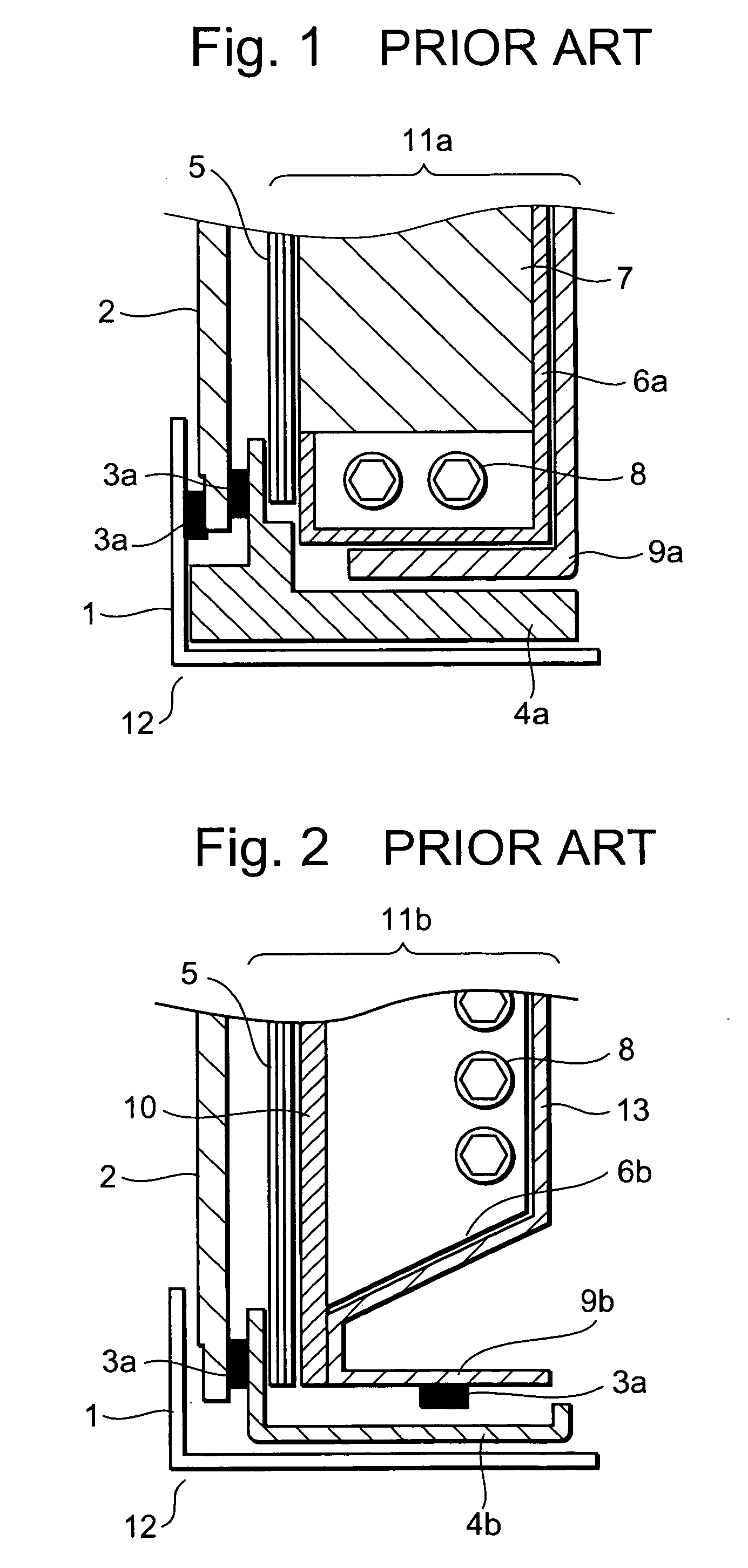
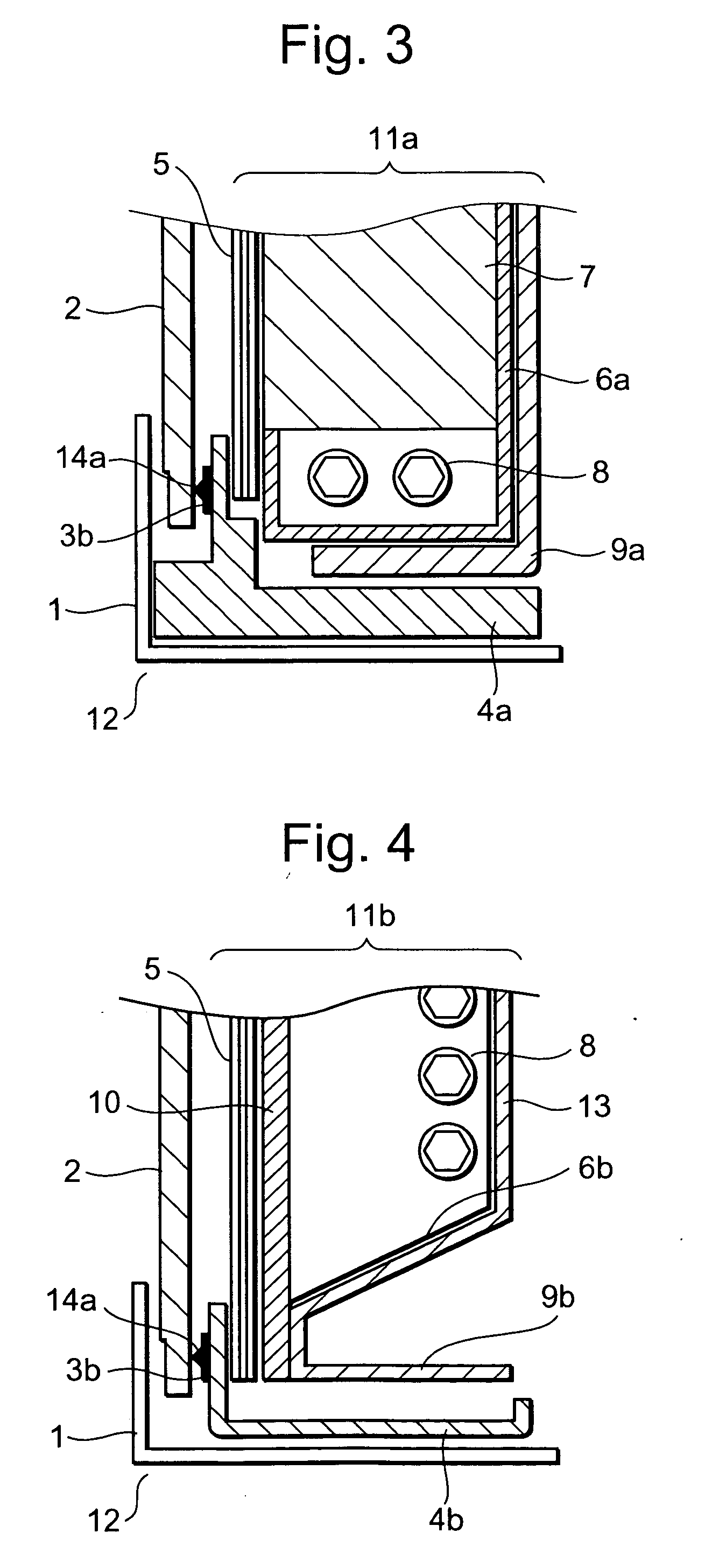
[0057]FIG. 4 is a cross-sectional view of a liquid crystal display module for describing a second example in the present invention. As shown in FIG. 4, the liquid crystal display module 12 of the second example in this embodiment represents a case where illuminating means is of a direct back light type. This liquid crystal display module 12 includes the liquid crystal panel 2, a direct back light 11b, and a frame structure having the upper frame 1, an intermediate frame 4b, and a lower frame 9b for surrounding and protecting the respective members. In particular, inside the lower frame 9b, the direct back light 11b includes the lamps 8 arranged at the bottom, and a reflector 6b for reflecting light emitted from the lamps 8. Further, on the lower frame 9b, the direct back light 11b includes a diffuser 10 and the optical sheet 5 for directing the reflected light efficiently to the liquid crystal panel 2 side. Here, a lamp holder set 13, which is formed by mounting the lamps 8 and the ...

third embodiment

[0067]FIG. 7 is a cross-sectional view of a liquid crystal display module for describing a first example in the present invention. Meanwhile, FIG. 8 is a cross-sectional view of a liquid crystal display module for describing a second example in the third exemplary embodiment of the present invention.

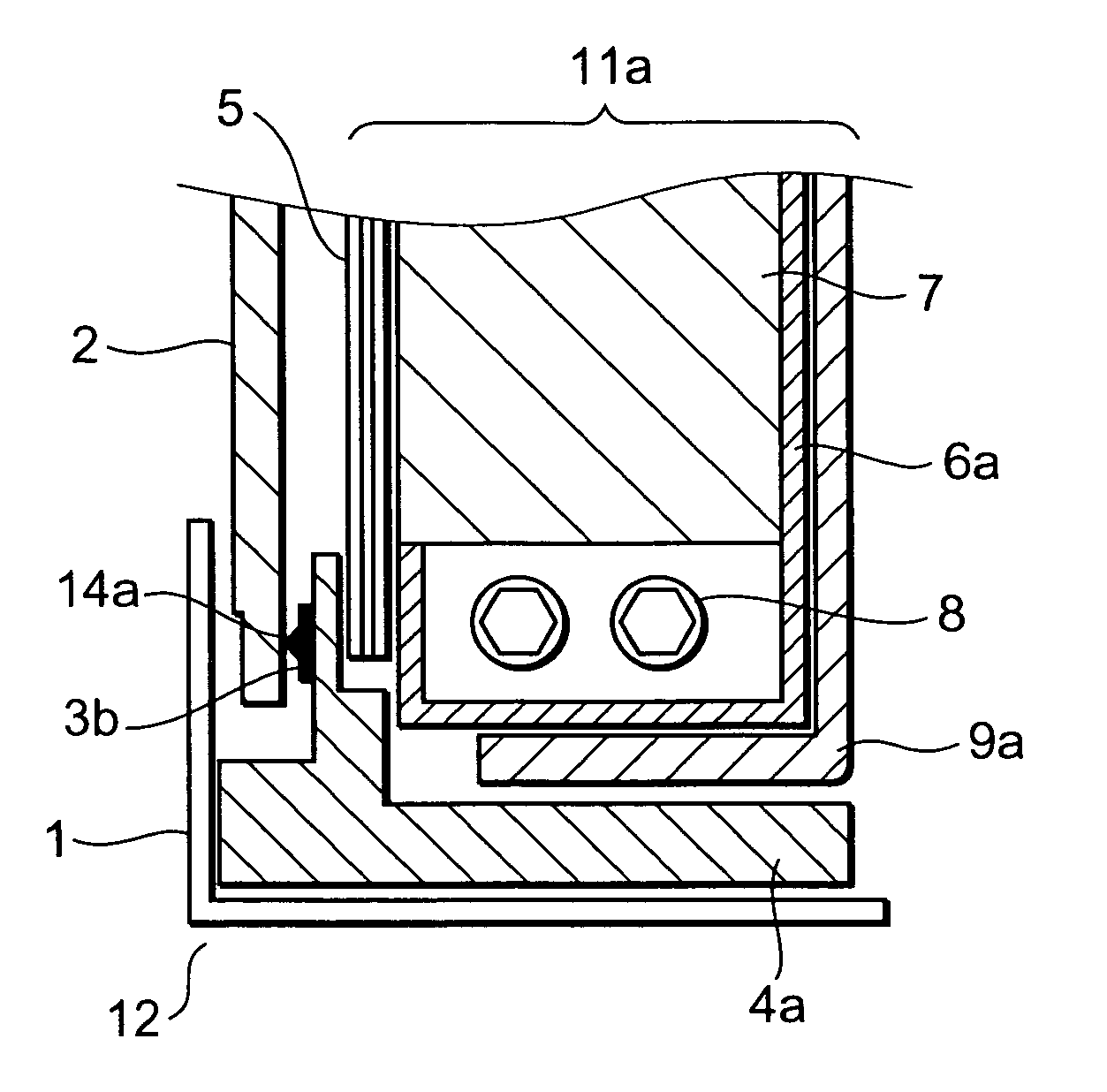
[0068] As shown in FIG. 7, the liquid crystal display module 12 in this embodiment includes both of the elastic member 3b described in the first exemplary embodiment and the elastic member 3c described in the second exemplary embodiment. The liquid crystal display module 12 of this embodiment includes a liquid crystal panel 2, a side type back light 11a, a frame mechanism, and the two elastic members 3b and 3c. The side type back light 11a is formed by housing lamps 8, a reflector 6a, and an optical waveguide 7 inside a lower frame 9a and disposing an optical sheet 5 on the reflector 6a. Specifically, this embodiment adopts the structure in which the elastic member 3b is fixed to the fro...


PUM

PropertyMeasurementUnit
flexibilityaaaaaaaaaa
elasticaaaaaaaaaa
elasticityaaaaaaaaaa

Abstract

An elastic member (3b) is fixed to a space between a front surface of an intermediate frame (4a) and a rear surface of a liquid crystal panel (2) constituting a liquid crystal display module (12), or a space between a rear surface of an upper frame (1) and the rear surface of the liquid crystal panel (2) constituting the liquid crystal display module (12). Alternatively, the elastic members (3b) are fixed to both of the spaces. A peak portion (14a) of the elastic member (3b) is formed to possess a flexible structure. The liquid crystal display module is configured to hermetically seal the space between a back light (11a) and the liquid crystal panel (2), the space between the upper frame (1) and the liquid crystal panel (2), or both of the spaces.

Description

BACKGROUND OF THE INVENTION [0001] 1. Field of the Invention [0002] The present invention relates to a liquid crystal display module and a back light for the same. More specifically, the present invention relates to a liquid crystal display module and a back light for the same having a dust-proof structure. [0003] 2. Description of the Related Art [0004] A display device configured to integrate a liquid crystal panel with an illumination panel to enhance a dust-proof effect of a liquid crystal display module has been disclosed in Japanese Unexamined Patent Publication No. 2003-005658 (p. 2-3, FIG. 3 and FIG. 5), for example. [0005] The display device disclosed in the publication includes a display unit which maintains a constant space between a display panel and an illumination panel for illuminating the display panel by use of a frame body. This display unit is covered with a protection cover unit. In particular, the frame body is made of a flexible member and protrusions are integ...

Claims


Application Information

Patent Timeline
Patent Type & Authority Applications(United States)
IPC IPC(8): F21S2/00F21V8/00G02F1/1333F21Y103/00G02F1/13G02F1/133G02F1/1335G02F1/13357G09F9/00G09F9/35
CPCG02F1/133308G02F1/133604G02F1/133608G02F2201/503G02F2001/133311G02F2001/133317G02F1/133615G02F1/133317G02F1/133311C23C8/70C23C8/02C23C8/80F01D5/288
Inventor SUGAWARA, HIDEAKI
Owner BEIHAI HKC OPTOELECTRONICS TECH CO LTD
Why Eureka
Try Eureka