Radar device

a radar and device technology, applied in the field of radar devices, can solve the problems of large limiting factor and decrease in the performance of radar devices, and achieve the effect of reducing the limiting factor in the optical system design

Inactive Publication Date: 2005-09-29
DENSO CORP
View PDF7 Cites 23 Cited by
  • Summary
  • Abstract
  • Description
  • Claims
  • Application Information

AI Technical Summary

Benefits of technology

[0009] With this configuration, an object detectable distance range of the radar device is less likely to be reduced. Moreover, the noise component is detected using the noise component signal output section and the selector section. Thus, the consideration of the predetermined rotation angle is not required in optical system design unlike the prior art and limiting factors in the optical system design can be reduced.

Problems solved by technology

As a result, performance of the radar device decreases.
However, the consideration of the predetermined rotation angle is required in optical system design and it is a large limiting factor in the optical system design.

Method used


Image

  • Radar device
  • Radar device
  • Radar device

Examples


first embodiment

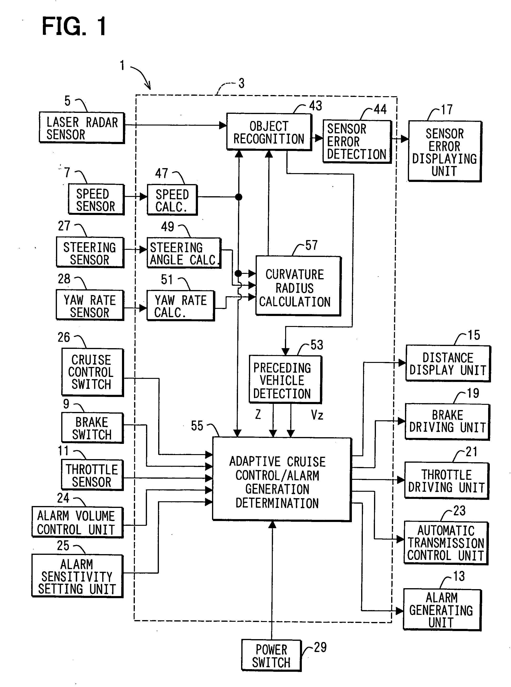
[0028] Referring to FIG. 1, a vehicle control system 1 includes an object recognition and cruise control electronic control unit (ECU) 3. The ECU 3 has a microcomputer as a main component, and has an input and output interface (I / O) and various driving and detection circuits.

[0029] The ECU 3 receives signals from a laser radar sensor 5, a speed sensor 7, a brake switch 9, and a throttle sensor 11. The radar sensor 5 is a radar device. The ECU 3 outputs driving signals to an alarm generating unit 13, a distance displaying unit 15, a sensor error displaying unit 17, a brake actuating unit 19, a throttle actuating unit 21, and an automatic transmission control unit 23.

[0030] An alarm volume control unit 24, an alarm sensitivity setting unit 25, a cruise control switch 26, a steering sensor 27, and a yaw rate sensor 28 are connected to the ECU 3. The alarm volume control unit 24 controls a volume of an alarm sound. The alarm sensitivity setting unit 25 controls sensitivity in an alarm...

second embodiment

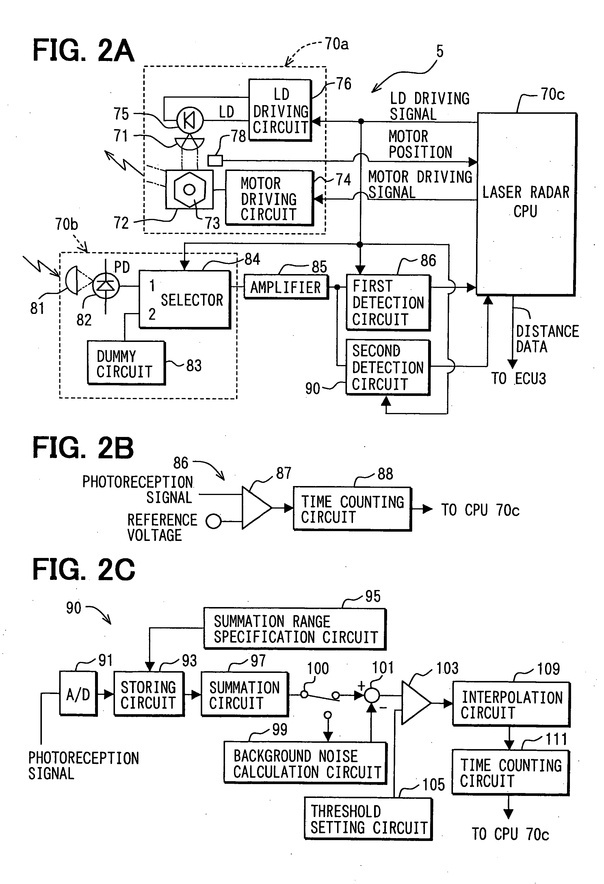
[0075] Referring to FIG. 10, a laser radar sensor 150 includes a light receiving circuit 170b. Other configurations are the same as the first embodiment, and therefore only the configuration of the light receiving circuit 170b will be discussed.

[0076] The light receiving circuit 170b does not include the dummy circuit 83 and the selector 84 that are included in the light receiving circuit 70b of the first embodiment. The photoreception signals outputted from the photoreceptor 82 are directly inputted to the amplifier 85. Furthermore, a light emitting device 140, for example, a light emitting diode, is arranged adjacent to the photoreceptor 82.

[0077] The light emitting device 140 emits light toward the photoreceptor 82 and the photoreceptor 82 is lighted with high intensity of light. Thus, the photoreceptor 82 can be saturated, and the photoreceptor 82 does not output signals in response to incident light when light is emitted from the light emitting device 140. Namely, the photore...

third embodiment

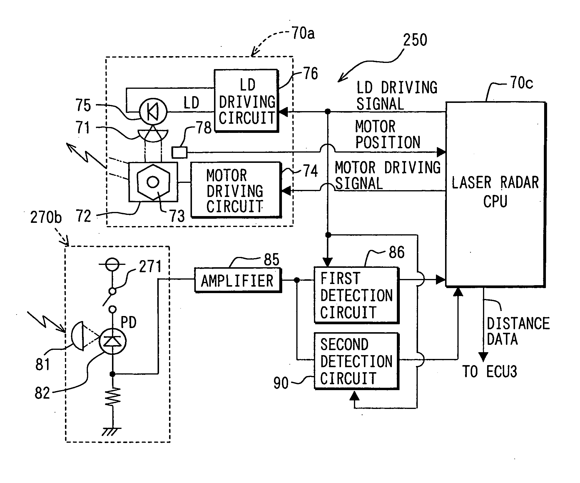
[0080] Referring to FIG. 11, a laser radar sensor 250 includes a light receiving circuit 270b. Other configurations are the same as the first embodiment, and therefore only the configuration of the light receiving circuit 270b will be discussed.

[0081] The light receiving circuit 270b does not include the dummy circuit 83 and the selector 84 that are included in the light receiving circuit 70b of the first embodiment. The photoreception signals outputted from the photoreceptor 82 are directly inputted to the amplifier 85. Furthermore, a switching device 271, for example, a transistor, is connected in a power supply line for feeding bias current to the photoreceptor 82.

[0082] The bias current supply to the photoreceptor 82 is controlled according to turning on and off of the switching device 271. Levels of the photoreception signals, namely, output voltages, corresponding intensity of incident light of the photoreceptor 82 greatly changes according to the bias current whether it is ...


PUM


Abstract

A laser radar sensor includes a photoreceptor, a dummy circuit, an amplifier, a selector, and the first and the second detection circuits. A photoreception signal outputted from the photoreceptor and an output signal of the dummy circuit are amplified by the amplifier, and inputted to the second detection circuit. A noise component included in the photoreception signal based on the output signal of the dummy circuit when distance detection is not performed. The distance detection is performed based on the reception signal from which the noise component is removed. As a result, a reduction in detectable distance of the laser radar sensor is less likely to occur. Furthermore, the noise component is detected using the dummy circuit and the selector. Thus, the consideration of the predetermined rotation angle is not required in optical system design and limiting factors in the optical system design can be reduced.

Description

CROSS REFERENCE TO RELATED APPLICATION [0001] This application is based on and incorporates herein by reference Japanese Patent Application No. 2004-89164 filed on Mar. 25, 2004. FIELD OF THE INVENTION [0002] The present invention relates to a radar device. BACKGROUND OF THE INVENTION [0003] A vehicular radar device that detects an object ahead of a vehicle is proposed in JP-A-2002-40139. The radar device emits light waves or millimeter waves forward and detects an object based on reflected waves. This kind of radar device is used in a warning system that provides a warning when the vehicle becomes close to an object in front, such as a vehicle in front. It is also used in a speed control system that controls a vehicle speed to maintain a predetermined distance to a vehicle in front. [0004] In the radar device, a laser diode emits laser beams as outgoing waves. The laser beams are reflected with a rotating polygon mirror. Multiple laser beams are emitted in a predetermined range wit...

Claims


Application Information

Patent Timeline
Patent Type & Authority Applications(United States)
IPC IPC(8): G01S7/48G01S17/931G01B9/02G01C3/08G01S7/497G01S13/00
CPCG01C3/08G01S2007/4975G01S17/936G01S7/497G01S17/931
Inventor HOASHI, YOSHIAKI
Owner DENSO CORP
Why Eureka
Try Eureka