Position detecting device

Inactive Publication Date: 2005-09-29
FUJI PHOTO OPTICAL CO LTD
View PDF7 Cites 6 Cited by
  • Summary
  • Abstract
  • Description
  • Claims
  • Application Information

AI Technical Summary

Benefits of technology

[0008] An object of the invention is to provide a position detecting device which can carry out high-precision and high-resolution position detection by using an incremental type encoder and also carry out initialization processing in a short time when power is turned on, so that position detection can be effectively performed just after the power is turned on.
[0011] According to the present invention, the incremental type encoder is used, and thus the position detection can be carried out inexpensively with high precision and high resolution. Furthermore, in the initialization of the count value of the encoder when power is turned on, the control target is moved to a position at which a desired initialization signal is output without moving the control target greatly, whereby the count value can be properly set to the predetermined value corresponding to the position of the control target. Therefore, the initialization of the count value can be performed in a short time, and the position detection can be effectively carried out just after power is turned on.
[0015] (5) The position detecting device is preferably characterized in that in the invention of (3), the count value setting means detects the output value of the position detecting sensor when initialization of the count value is started, and moves the control target to a position where an initialization signal identified by the nearest value out of the values of the identification information stored in the current value storage means is output. When the position detecting sensor is used as in the case of (3), the control target can be moved to the nearest position at which the initialization signal is output to initialize the count value by detecting the current value of the control target (which is not necessarily coincident with the original current value) with the position detecting sensor when the initialization of the count value is started. Accordingly, the initialization of the count value can be carried out in a shorter time.
[0019] According to the present invention, the position detection is carried out by using the incremental type encoder, and thus the position detection can be performed inexpensively with high precision and high resolution. Furthermore, the initialization of the count value of the encoder can be carried out in a short time.

Problems solved by technology

That is, when the potentiometer is used as the position detecting sensor, a high-precision potentiometer is needed, which increases the cost.
Furthermore, even the high-precision potentiometer has a limitation in the linearity of an output voltage to a detected position (detected angle), and thus the precision of the position detection is restricted.
Furthermore, when digital processing is needed, it is required to convert the output voltage of the potentiometer to a digital signal by an A / D converter, and thus the A / D converter is also required to have high precision, resulting in increase in cost.
Therefore, there is a drawback that a time needed for the original-point returning operation is needed when power is turned on.
When the absolute type encoder is used, it is required to have high resolution, and thus it has a drawback that the cost is increased.
Furthermore, there is also a limit in the resolution of the absolute type encoder, and also it needs parallel outputs.
Therefore, it has a drawback that there are required cables and input terminals whose numbers correspond to the number of bits.

Method used


Image

  • Position detecting device
  • Position detecting device
  • Position detecting device

Examples


Embodiment Construction

[0026] Preferred embodiments of a position detecting device according to the present invention will be described hereunder with reference to the accompanying drawings.

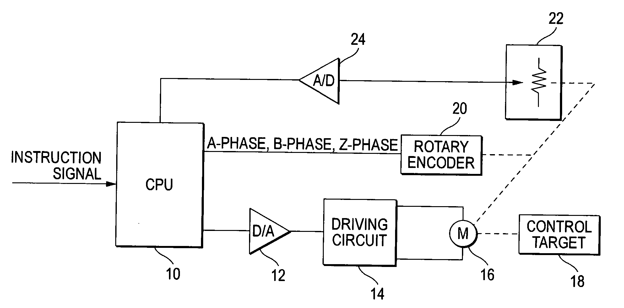
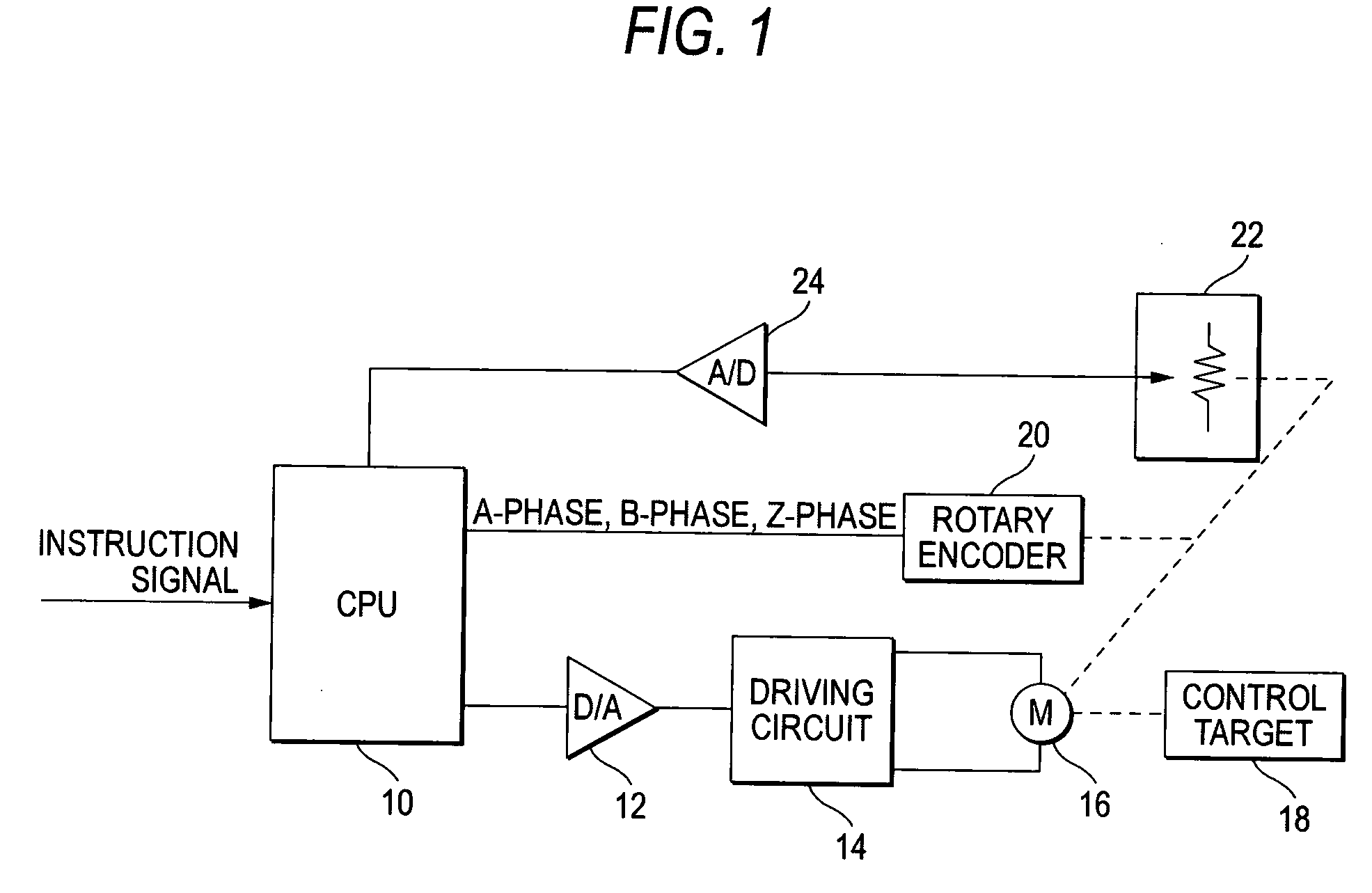
[0027]FIG. 1 is a diagram showing the construction of a servo circuit to which the present invention is applied. The servo circuit shown in FIG. 1 controls a desired control target 18 by a motor 16, and it sets the position of the control target 18 as a control amount and controls the control target 18 so that the control amount is equal to a target value supplied by an instruction signal. An application range of this servo circuit is not limited to a specific field. Particularly when it is applied to a camera platform system for supporting a television system or television camera, a movable lens group of the television lens, a pan mechanism of the camera platform system, a tilt mechanism, etc. are control targets, and an instruction signal is supplied from a predetermined controller.

[0028] In FIG. 1, CPU 10 is suppl...


PUM


Abstract

A position detecting device in which a count value is incremented or decremented on the basis of a pulse output from an encoder every predetermined shift amount of a control target to thereby detect a current value representing a current position of the control target as the count value, is characterized by comprising: initialization signal output means for outputting an initialization signal representing an initialization position at plural positions of a movable range of the control target when the movable range of the control target is restricted, or at plural positions of an operating range of integer times of a period when the movable range of the control target is not restricted and the same state is repeated at the period concerned; current value storing means for storing, in association with identification information for identifying each initialization signal, the current value of the control target at each position where the initialization signal is output by each initialization signal output means; and count value setting means for moving the control target to a position where some initialization signal is output from the initialization signal output means at the initialization time of the count value, and achieving the current value corresponding to identification information for identifying the initialization signal from the current value storage means, and setting the current value thus achieved as the count value.

Description

BACKGROUND OF THE INVENTION [0001] 1. Technical Field of the Invention [0002] The present invention relates to a position detecting device, and particularly to a position detecting device used to detect the position of a control target in a servo device. [0003] 2. Description of the Related Art [0004] A servo device (servo circuit) for servo-driving a motor in accordance with an instruction signal from a controller has been hitherto used in a lens driving operation of a television lens, a pan / tilt driving operation of a camera platform for supporting the television camera or the like. The servo circuit uses a position detecting sensor for detecting the position of a control target to be driven by the motor, and a potentiometer or encoder has been hitherto used as such a position detecting sensor. JP-A-7-230031 describes a position detecting device using a potentiometer. [0005] However, in connection with a case where a potentiometer is used as a position detecting sensor and a case ...

Claims


Application Information

Patent Timeline
IPC IPC(8): G01D5/245G01B7/30
CPCG01D5/165G01D5/2454G01D5/2449G01D5/24452G01D18/001
Inventor SUZUKI, AKIHIROCHO, TADAYOSHI
Owner FUJI PHOTO OPTICAL CO LTD
Why Eureka
Try Eureka