
Distortion correction device and image sensing device provided therewith

a technology of distortion correction and image sensing, which is applied in image enhancement, instruments, television systems, etc., can solve the problems of affecting the image position of the solid-state image sensor, requiring a large-capacity memory, and cannot deal with all types of distortion, so as to reduce the amount of data, reduce the amount of calculation, and achieve high accuracy. approximation

Active Publication Date: 2005-09-29
XACTI CORP
View PDF8 Cites 52 Cited by
  • Summary
  • Abstract
  • Description
  • Claims
  • Application Information

AI Technical Summary

Benefits of technology

[0013] According to the present invention, several distortion data, i.e., discrete points on an image height-distortion curve, are stored, and, according to a plurality of distortion data near the image height of the output coordinate position, it is possible to calculate the approximation formula representing the image height-distortion curve near the image height of the output coordinate position. In this way, it is possible to reduce the amount of data that needs to be stored for the reproduction of the image height-distortion curve. Moreover, it is possible to reduce the amount of calculation that needs to be performed to obtain a highly accurate approximation curve, and thus to achieve distortion correction with high accuracy.
[0014] Moreover, edge enhancement can be performed simultaneously, and the parameters used for that purpose can be varied according to the image height, distortion, or coordinate position. Thus, it is possible to perform edge enhancement that suits given coordinate positions, and thereby prevent loss of resolution resulting from interpolation. Moreover, for different chrominance signals, approximation formulae based on different image height-distortion curves can be calculated. Thus, simultaneously with distortion correction on coordinate positions, it is possible to correct chromatic aberrations resulting from different refractive indices for different colors. Furthermore, it is possible to set the distortion data according to the degree in which to distort the image represented by the outputted image signal. This makes it easy to generate an image signal that suits the way an image desired to be displayed.

Problems solved by technology

When an image is sensed with a solid-state image sensing device such as a CCD (charge-coupled device) or CMOS sensor through an optical lens, the aberrations produced by the optical lens cause the imaging positions on the solid-state image sensor to be displaced.
Disadvantageously, however, this image sensing device requires a large-capacity memory for the storage of distortion values corresponding to different pixel positions.
This, however, cannot deal with all types of distortion, because not all distortion is proportional to the square of the image height.

Method used


Image

  • Distortion correction device and image sensing device provided therewith
  • Distortion correction device and image sensing device provided therewith
  • Distortion correction device and image sensing device provided therewith

Examples


first embodiment

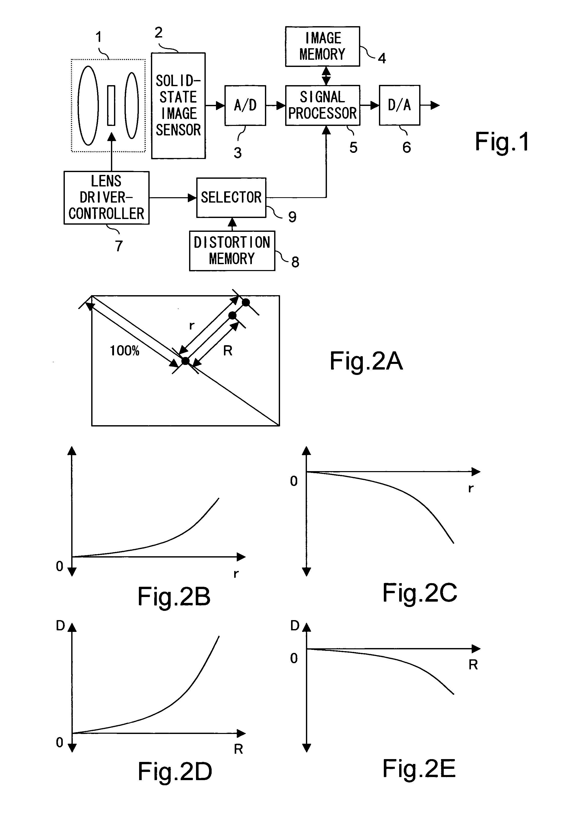
[0032] A first embodiment of the present invention will be described below with reference to the drawings. FIG. 1 is a block diagram showing the internal configuration of the image sensing device of this embodiment. FIG. 4 is a block diagram showing the internal configuration of the signal processor provided in the image sensing device of this embodiment.

[0033] The image sensing device shown in FIG. 1 is provided with: an optical system 1 that receives the light from a subject and that is composed of a plurality of lenses; a solid-state image sensor 2, such as a CCD or CMOS sensor, that receives the light incident thereon through the optical system 1 and that outputs an electrical signal commensurate with the amount of incident light; an A / D converter 3 that converts the image signal outputted from the solid-state image sensor 2 into a digital signal; an image memory 4 that temporarily stores the image signal; a signal processor 5 that reads out the image signal stored in the image...

second embodiment

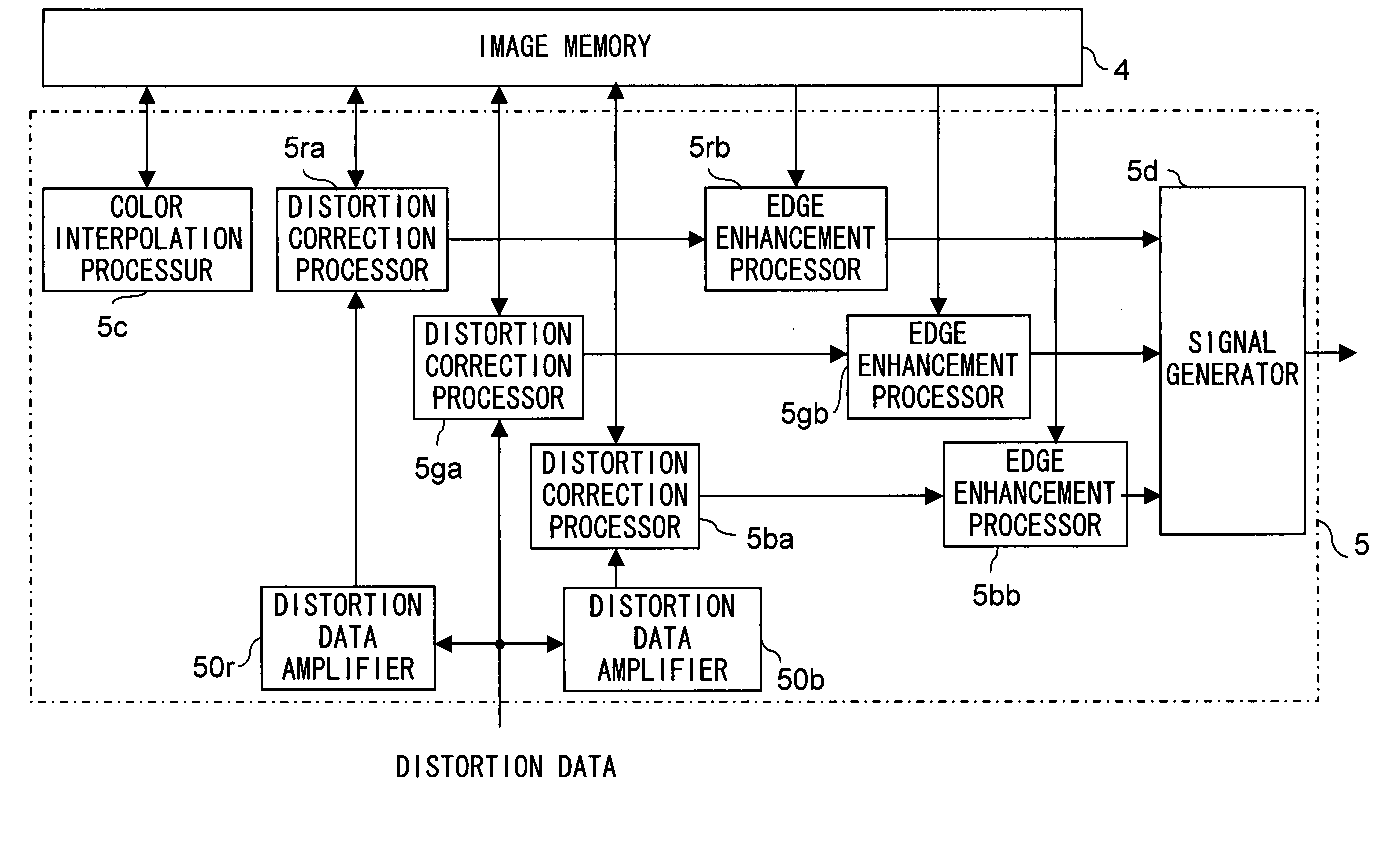
[0059] A second embodiment of the present invention will be described below with reference to the drawings. The image sensing device of this embodiment is, as in the first embodiment, configured as shown in FIG. 1. FIG. 8 is a block diagram showing the internal configuration of the signal processor provided in the image sensing device of this embodiment. The image sensing device of this embodiment differs from the image sensing device of the first embodiment in that the signal processor 5 performs not only distortion correction but also edge enhancement. Thus, in this embodiment, except the signal processor 5, all the circuit blocks are configured in the same manners and operate in the same manners as in the first embodiment; therefore, for their explanations, those given earlier in connection with the first embodiment are to be referred to, and no detailed explanations will be repeated.

[0060] In the image sensing device of this embodiment, as shown in FIG. 8, the signal processor ...

third embodiment

[0074] A third embodiment of the present invention will be described below with reference to the drawings. The image sensing device of this embodiment is, as in the first embodiment, configured as shown in FIG. 1. FIG. 12 is a block diagram showing the internal configuration of the signal processor provided in the image sensing device of this embodiment. The image sensing device of this embodiment differs from the image sensing device of the second embodiment in that the signal processor 5 performs not only distortion correction and edge enhancement but also chromatic aberration correction. Thus, in this embodiment, except the signal processor 5, all the circuit blocks are configured in the same manners and operate in the same manners as in the first and second embodiments; therefore, for their explanations, those given earlier in connection with the first and second embodiments are to be referred to, and no detailed explanations will be repeated.

[0075] In the image sensing device ...


PUM


Abstract

Distortion data discretely stored in a distortion data memory 8 are read out by a selector 9 and fed to a signal processor 5. For each coordinate position, the signal processor 5 calculates an approximation formula representing an image height-distortion curve based on the distortion data fed thereto, and performs distortion correction based on the approximation formula.

Description

[0001] This application is based on Japanese Patent Application No. 2004-94595 filed on Mar. 29, 2004, the contents of which are hereby incorporated by reference. BACKGROUND OF THE INVENTION [0002] 1. Field of the Invention [0003] The present invention relates to a distortion correction device that corrects an image signal obtained by image sensing for distortion produced by the lens used for the image sensing, and to an image sensing device provided with such a distortion correction device [0004] 2. Description of Related Art [0005] When an image is sensed with a solid-state image sensing device such as a CCD (charge-coupled device) or CMOS sensor through an optical lens, the aberrations produced by the optical lens cause the imaging positions on the solid-state image sensor to be displaced. Thus, if the image is reproduced for display directly from the image signal outputted from the solid-state image sensing device, the displayed image appears deformed. This deformation appearing...

Claims


Application Information

Patent Timeline
IPC IPC(8): G06T1/00H04N1/04G06T3/00H04N1/387H04N1/409H04N1/58H04N5/232H04N5/235H04N5/238
CPCH04N1/387H04N9/045H04N5/3572H04N1/58H04N25/61H04N23/843
Inventor OKADA, SEIJIMORI, YUKIOKINOSHITA, ATSUFUMI
Owner XACTI CORP
Features
  • Generate Ideas
  • Intellectual Property
  • Life Sciences
  • Materials
  • Tech Scout
  • Unparalleled Data Quality
  • Higher Quality Content
  • 60% Fewer Hallucinations
Learn More