
Duplex scanner

Active Publication Date: 2005-09-29
AVISION
View PDF10 Cites 9 Cited by
  • Summary
  • Abstract
  • Description
  • Claims
  • Application Information

AI Technical Summary

Benefits of technology

[0010] It is therefore an object of the invention to provide a duplex scanner. With the design of a power source to output feedback signal, the duplex scanner according to the invention, which can resolve problems frequently encountered such as loss of step-synchronism, motor stall, high operating temperature, vibration, noises and low scanning speed when a conventional open-loop control stepper motor is adopted, meets the requirements of high rotation rate, high load, high load variation, little vibration, low noises and high scanning speed.

Problems solved by technology

However, the document turning mechanism of either type of the simplex scanners would only increase scanning time.
The stepper motor adopts an open-loop control method, and will easily lose step-synchronism when exceeding allowed pull-in torque due to a high rotation rate.
If the stepper motor loses the step-synchronism for too long, a motor stall will occur and becomes an unsolvable problem.
Besides, if the stepper motor adopts micro-stepping driving method, the positional accuracy is normally hard to achieve the required smooth level.
Besides, due to limitation imposed by the internal structure of the stepper motor, a stepper motor normally is not functional at a rotational speed over 5000 rpm, and has poor torque characteristics at any high rotational speed.
To maintain a maximum holding torque, an open-loop controlled stepper motor is normally operated under fully powered state, resulting in a high operating temperature.
The stepper motor has significant noises and mechanic vibration problems when operating in full step state, especially at a low rotational speed.
Moreover, the resonant band of the stepper motor is too many and too wide, such that when other mechanisms are incorporated, resonance and noises are easily induced.
The open-loop controlled stepper motor will be inadequate to accommodate scanner's future requirements, such as high rotational speed, high load, high load variation, little vibration, low noises and high scanning speed.

Method used


Image

  • Duplex scanner
  • Duplex scanner
  • Duplex scanner

Examples


embodiment one

Preferred Embodiment One

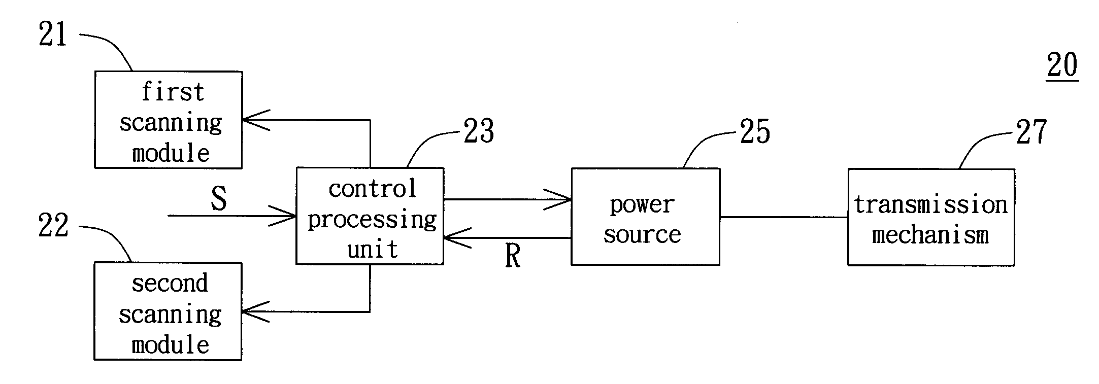
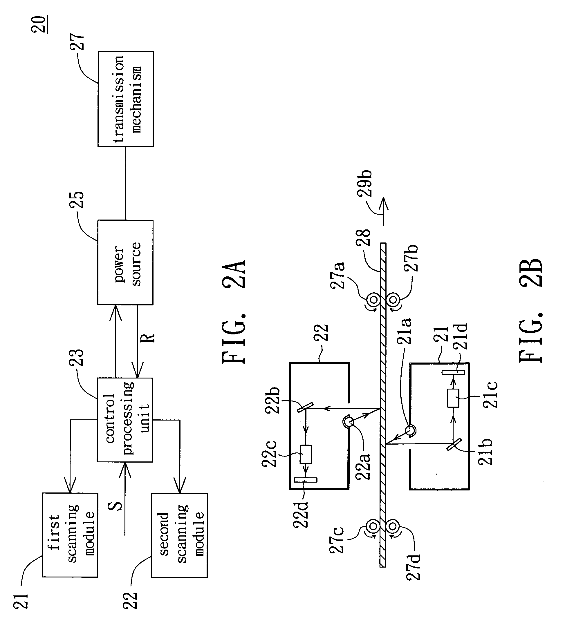
[0022] Referring to FIG. 2A, a block diagram of duplex scanner according to preferred embodiment one of the invention is shown. In FIG. 2A, a duplex scanner 20 at least comprises a first scanning module 21, a second scanning module 22, a control processing unit 23, a power source 25 and a transmission mechanism 27. As shown in FIG. 2B, the first scanning module 21 is for scanning a front side of a to-be-scanned document 28 and capturing the front side image of the to-be-scanned document 28. The second scanning module 22 is for scanning a back side of the to-be-scanned document 28 and capturing the back side image of the to-be-scanned document 28. The transmission mechanism 27 is for enabling the to-be-scanned document 28 to move relatively to the first scanning module 21 and the second scanning module 22.

[0023] Assuming that the first scanning module 21 and the second scanning module 22 in FIG. 2B remain still, then the transmission mechanism 27 in FIG. 2A i...

embodiment two

Preferred Embodiment Two

[0027] Referring to FIG. 3A, a block diagram of duplex scanner according to preferred embodiment two of the invention is shown. In FIG. 3A, a duplex scanner 40 at least comprises a first scanning module 41, a second scanning module 44, control processing unit 43, a first power source 45, a second power source 46, a first transmission mechanism 47 and a second transmission mechanism 48. As shown in FIG. 3B, the first scanning module 41 is for scanning a front side of a to-be-scanned document 49 and capturing the front side image of the to-be-scanned document 49. The second scanning module 44 is for scanning a back side of the to-be-scanned document 49 and capturing a back side image of the to-be-scanned document 49. The first transmission mechanism 47 is for moving the first scanning module 41, while the second transmission mechanism 48 is for moving the to-be-scanned document 49.

[0028] The duplex scanner 40 in FIG. 3B can be a flat-bed type duplex scanner in...

embodiment three

Preferred Embodiment Three

[0031] Referring to FIG. 4, a block diagram of duplex scanner according to preferred embodiment three of the invention is shown. The duplex scanner 50 in present preferred embodiment differs with the duplex scanner 40 in preferred embodiment in the first control processing unit 53 and the second control processing unit 54, as for other similar constituting elements, the same labeling are used and are not repeated here. In FIG. 4, either both the first control processing unit 53 and the second control processing unit 54 can receive the scan command S, or one of the first control processing unit 53 and the second control processing unit 54 will receive the scan command S. The first control processing unit 53 will receive the scan command S and determine whether the first scanning module 41 has arrived at the pre-determined position or not. If the first scanning module 41 has not arrived at the pre-determined position, the first control processing unit 53 will...


PUM


Abstract

A duplex scanner comprising a first scanning module, a second scanning module, a transmission mechanism, a power source and a control processing unit is provided. The first scanning module scans a front side of a to-be-scanned document and captures a front side image of the to-be-scanned document. The second scanning module scans a back side of the to-be-scanned document and captures a back side image of the to-be-scanned document. The transmission mechanism moves the to-be-scanned document relatively to the first scanning module and the second scanning module. The power source outputs at least a feedback signal while driving the transmission mechanism. The control processing unit receives a scan command and accordingly controls the power source to drive the transmission mechanism. The control processing unit receives the feedback signal and accordingly controls the first scanning module and the second scanning module to proceed duplex scan.

Description

[0001] This application claims the benefit of Taiwan application Serial No. 93108027, filed Mar. 24, 2004, the subject matter of which is incorporated herein by reference. BACKGROUND OF THE INVENTION [0002] 1. Field of the Invention [0003] The invention relates in general to a scanner, and more particularly to a duplex scanner having two scanning modules. [0004] 2. Description of the Related Art [0005] Along with the rapid advance in technology, the integration and application of multi-media have become more and more popular. Multi-media refer to data contents of various data types such as texts, images, sounds etc. In order to present data through multi-media, various devices for capturing images or sounds have been developed. For instance, scanner is one of most commonly used tools for capturing images. [0006] Referring to FIG. 1A, a block diagram of a conventional sheet-fed type simplex scanner with a stepper motor is shown. In FIG. 1A, scanner 10 comprises a charge-coupled devic...

Claims


Application Information

Patent Timeline
IPC IPC(8): H04N1/00H04N1/04H04N1/203
CPCH04N1/00885H04N2201/04724H04N1/203
Inventor CHEN, YEN-CHENGCHEN, SHING-CHIA
Owner AVISION
Features
  • Generate Ideas
  • Intellectual Property
  • Life Sciences
  • Materials
  • Tech Scout
  • Unparalleled Data Quality
  • Higher Quality Content
  • 60% Fewer Hallucinations
Learn More